


 Abstract
 HTML
HTML Reference
 Related
 PDF
PDF


-
Imaging Atmospheric Cherenkov Telescopes (IACTs) study cosmic rays by indirectly observing the Cherenkov radiation produced by Extensive Air Showers (EAS). Although existing IACT arrays such as H.E.S.S. [1], MAGIC [2], and CTA [3] have the advantages of high sensitivity and high angular resolution, the optical systems of these telescopes adopt reflective telescopes, which have limited effective observation FoV and are not conducive to the observation of transient and extended sources.
The HADAR project [4] is a refracting telescope array. Compared to traditional IACT reflector telescopes, refracting telescopes can effectively overcome the limitation of narrow FoV in traditional IACT arrays (the FoV traditional IACT arrays
$ \lt $ 0.024 sr [5−7], while HADAR is approximately 0.84 sr [4]). The Fresnel lens made of UVT-PMMA (UV-transmitting poly methyl methacrylate) exhibits high transmittance in the near ultraviolet band (290 – 430 nm), and possesses physical and engineering advantages such as a lightweight structure [8] (at 300 nm, the transmittance of 3 mm thick sheets exceeds 80%, while 8 mm thick sheets maintain no less than 70% transmittance; when the wavelength increases to approximately 370 nm, the transmittance within the 3 – 8 mm thickness range approaches 90%)[9], mature manufacturing technology, strong adaptability to low temperatures at high altitudes, and low maintenance costs. In this paper, the Fresnel lens is studied as an alternative solution for refractive telescope designs aiming at a wide FoV and a low-energy threshold.As the first step, this paper investigates and discusses whether the optical performance of the Fresnel lens unit has the potential to achieve a refractive telescope with a wide FoV and low-energy threshold comparable to that of the water lens. It evaluates and provides a range of optional parameters (diameter/focal length, tooth width and thickness, curved image surface and
$r_{80}$ , acceptance, etc.) that meet practical constraints. The second step will be based on this to carry out array simulation and optimization, refining the lens unit parameters and array layout within the aforementioned optional range, and determining the optimal lens unit and array scheme using comprehensive indicators such as effective area, angular resolution, and gamma source sensitivity. Internationally, there are already mature space/balloon platform experiments using the Fresnel lens for near-ultraviolet wide-field imaging, such as the Mini-EUSO with a square FoV of 44° and an angular resolution of about 0.9° in the JEM-EUSO series; the EUSO-Balloon with an FoV of about 11° and an angular resolution of about 0.2°; and the K-EUSO with a rectangular FoV of about 0.3 sr and an angular resolution of about 0.1° [10−12]. All three operate in the wavelength band of 290 – 430 nm, using UVT-PMMA Fresnel lenses, combined with thin and lightweight modular processes such as segmented assembly and diamond turning, to verify their engineering feasibility and imaging stability.This paper simulates and analyzes the influence of key parameters such as the radius of curvature, tooth width, and thickness of the Fresnel lens on the lens focal length and image spot. Five types of Fresnel lenses with the same focal length as the 5.0 m diameter water lens in the HADAR project are designed. The best focusing positions under different incident angles were extracted, and the curved image surface was constructed through fitting. Based on the curved image surface, the image area corresponding to Fresnel lenses of different diameters is calculated, and the required number of photomultiplier tube (PMT, with a radius of 2.5 cm) detection units arranged in a hexagonal close-packed pattern is given. Finally, the performance comparison of Fresnel lenses with different diameters and focal lengths is conducted.
-
The simulation was conducted using ZEMAX software with a parallel light source and a single wavelength. The ray density was set at a sampling interval of 0.025 within a unit circular aperture. The material of the Fresnel lens is UVT-PMMA, with 300 nm selected as the representative wavelength (the peak wavelength of atmospheric Cherenkov spectrum is approximately 300 nm), and the refractive index of the material n = 1.51.
We optimized the Fresnel lens by adjusting its thickness, radius of curvature, pitch, and tooth width (the lens configuration is shown in Figure 1). The simulation process is as follows:
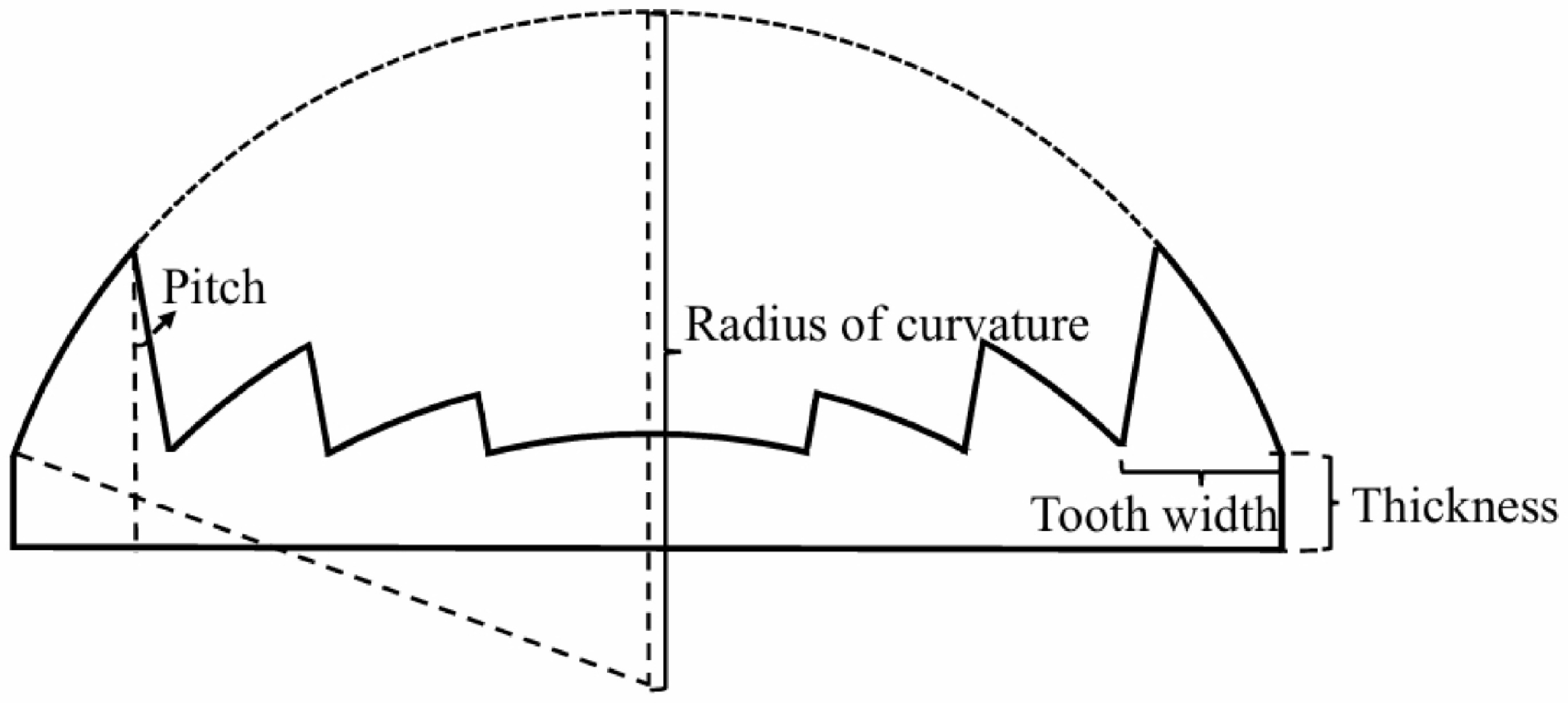
Figure 1. Configuration diagram of the Fresnel lens.
● Determine the basic configuration of the Fresnel lens.
In the simulation, we set the Fresnel lens tooth surface facing the light source. When the f-number (focal length to diameter ratio) is greater than 1.1, the transmission efficiency of the tooth surface facing the light source is slightly better than that of the plane facing the light source [13]. Ensure that the thickness of the lens is greater than the maximum tooth height, as shown in Figure 1. The tooth at the edge of the Fresnel lens is the highest. According to geometric relationships, the maximum tooth height can be calculated as,
$ d = \sqrt{R^2 - \left(\frac{D}{2}-\omega\right)^2}-\sqrt{R^2 - \left(\frac{D}{2}\right)^2}, $
(1) where R is the radius of curvature of the lens, D is the diameter of the lens, ω is the tooth width of the Fresnel lens.
In the simulation, we use the equal pitch Fresnel lens with a pitch set to 0°, aiming to reduce the interference on the focusing effect of the main optical surface.
● Calculation of initial parameters for the Fresnel lens.
Given the diameter of the Fresnel lens, several parameter values need to be calculated first as the initial conditions for the simulation. To ensure the optical efficiency of the Fresnel lens is high and its focal length is small, while also facilitating comparison with the 5.0 m diameter water lens in the HADAR project, the F-number of the lens is set to 1.36. From the paraxial imaging relation for a single spherical refracting surface, the lens makers' equation for a thin lens in air follows [14],
$ \frac{1}{f} = (n-1)\left(\frac{1}{R}-\frac{1}{R'}\right), $
(2) where f is the focal length. For the Fresnel lens, the first surface has a radius of curvature R, and the second surface is plane (
$ R'$ $ \to \infty $ ). We then obtain the relationship between the focal length and the radius of curvature,$ R = (n-1)f. $
(3) According to the empirical formula for the optimal tooth width of the Fresnel lens [13], when balancing the facet approximation error (the larger the tooth width, the greater the error) and the diffraction scattering (the smaller the tooth width, the stronger the scattering), the optimal tooth width is approximately,
$ \omega \approx 1.5 \sqrt{\lambda f}, $
(4) where λ is the wavelength of the incident light.
We plan to design five Fresnel lenses with diameters of 2.0 m, 2.5 m, 3.0 m, 4.0 m and 5.0 m for comparison with the water lens. In the HADAR project, the diameter of the water lens is 5.0 m. However, to achieve the specified image quality and angular resolution within the target FoV, an aperture stop with a diameter of 1.88 m is set behind the lens to limit the effective entrance pupil and suppress off-axis aberrations. The maximum projected diameter of the aperture stop on the lens is only 2.5 m. We take 2.5 m as the equivalent effective diameter benchmark for the water lens and then select four diameters of 2.0 m, 3.0 m, 4.0 m and 5.0 m. The five Fresnel lenses cover the acceptance, focal length and FoV range we are concerned about, which is convenient for the selection of lens units based on physical targets later.
● Design process of the Fresnel lens.
After determining the initial value and entrance pupil diameter, first assume the range of radius of curvature required for subsequent simulation, calculate the maximum tooth height, and set the thickness reasonably. Then, adjust the tooth width according to the optical path diagram to ensure that all rays can pass through the lens. Next, set the radius of curvature based on the required focal length and image spot size. Finally, calculate the lens thickness (taking into account the actual situation).
● Analyze the influence of the radius of curvature, tooth width and thickness of Fresnel lens on the focal length and image spot.
● The best focusing positions under different incident angles were extracted, and the curved image surface was constructed through fitting. Based on the curved image surface, the image area and the number of PMTs corresponding to Fresnel lenses of different diameters are calculated, and the performance of Fresnel lenses with different diameters and focal lengths is analyzed.
-
We quantify the size of the light spot using the equivalent radius (
$r_{80}$ ) that contains 80% of the photon energy, and provide the corresponding angular size$ \theta_{80} = \arctan(r_{80}/f) $ . When other parameters are fixed, by moving the position of the focal plane, the distance between the focal plane and the lens is considered as the focal length of the lens system when$r_{80}$ is at its minimum.Figure 2 shows the variation of the focal length and
$r_{80}$ of the Fresnel lens with the radius of curvature when the incident angle is 0°. It can be seen that among the geometric parameters of the Fresnel lens, the radius of curvature has the greatest impact on the focal length and$r_{80}$ . As the radius of curvature increases, the focal length increases and$r_{80}$ decreases. However, after the radius of curvature increases to a certain value,$r_{80}$ gradually stabilizes. The spherical aberration in geometrical optics mainly arises from the difference in imaging positions between marginal rays and paraxial rays. By applying the dominant primary spherical aberration term in the wave aberration expansion [15] to the Fresnel lens, one finds that for a fixed radius of curvature, a larger lens diameter leads to a faster growth of spherical aberration, and consequently a larger$r_{80}$ . When the lens diameter is fixed, the smaller the radius of curvature, the marginal rays are excessively refracted, and the focal point is significantly shifted relative to the paraxial rays, resulting in a large$r_{80}$ . As the radius of curvature increases, the higher-order bending effect weakens, the spherical aberration rapidly decreases, and$r_{80}$ decreases. Further increasing the radius of curvature, the lens approaches a plane almost, and the spherical aberration term gradually disappears.$r_{80}$ is ultimately limited by the inherent properties of the lens material (dispersion, absorption, scattering, etc.). From the overall trend,$r_{80}$ decreases with the increase of the radius of curvature. When the spherical aberration decreases to a certain extent, it tends to a stable lower limit jointly determined by the lens material and system parameters, and cannot be infinitely reduced.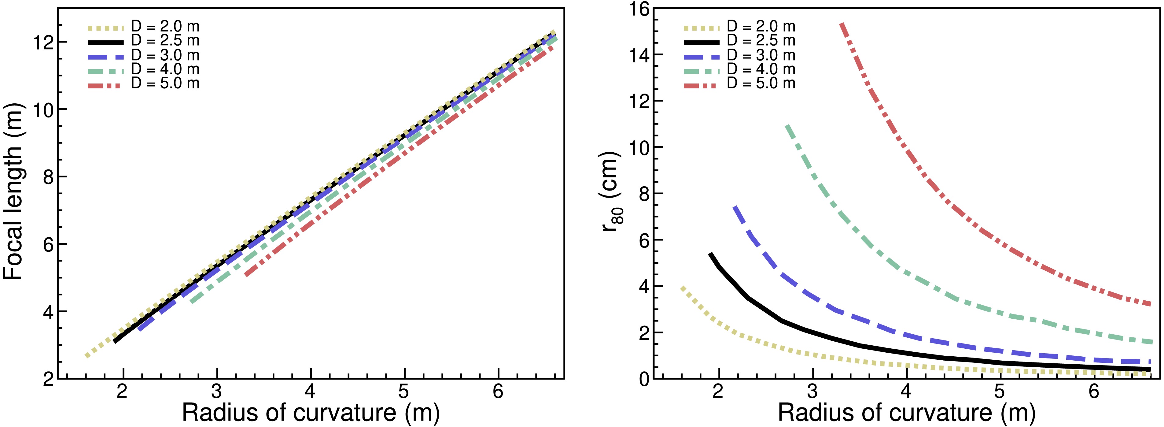
Figure 2. (color online) Effect of radius of curvature on focal length and
$r_{80}$ when the incident angle is 0°. The yellow dotted, black solid, blue dashed, green dash-dotted, and brownish-red dash-dot-dot lines denote Fresnel lenses with diameters of 2.0 m, 2.5 m, 3.0 m, 4.0 m, and 5.0 m, respectively.Figures 3 and 4 show the variations of the focal length and
$r_{80}$ of the Fresnel lens with respect to tooth width and thickness at incident angles of 0° and 20°, respectively. During the simulation process, the initial focal length of 6.8 m was selected for all five Fresnel lenses with different diameters. At incident angles of 0° and 20°, the tooth width and thickness of the Fresnel lens have a relatively small impact on the focal length and$r_{80}$ . This is because the Fresnel lens is not a continuous curved surface, and when the tooth width is different, a slight phase error occurs during the refraction process of light on the lens surface, causing$r_{80}$ to fluctuate slightly under certain tooth widths or incident angles. However, this fluctuation is much smaller than the change caused by the radius of curvature. Within the range of 0.20 - 2.00 mm,$r_{80}$ is basically unaffected by the tooth width. However, a smaller tooth width can improve the MTF (Modulation Transfer Function), making the image clearer, but it requires higher processing accuracy. Under conditions where the cost is acceptable, a smaller tooth width should be chosen [16]. The additional thickness is equivalent to the base thickness of the non-tooth surface, which is part of the structural support and has almost no impact on the imaging performance (the thicker the substrate, the lower the light transmittance).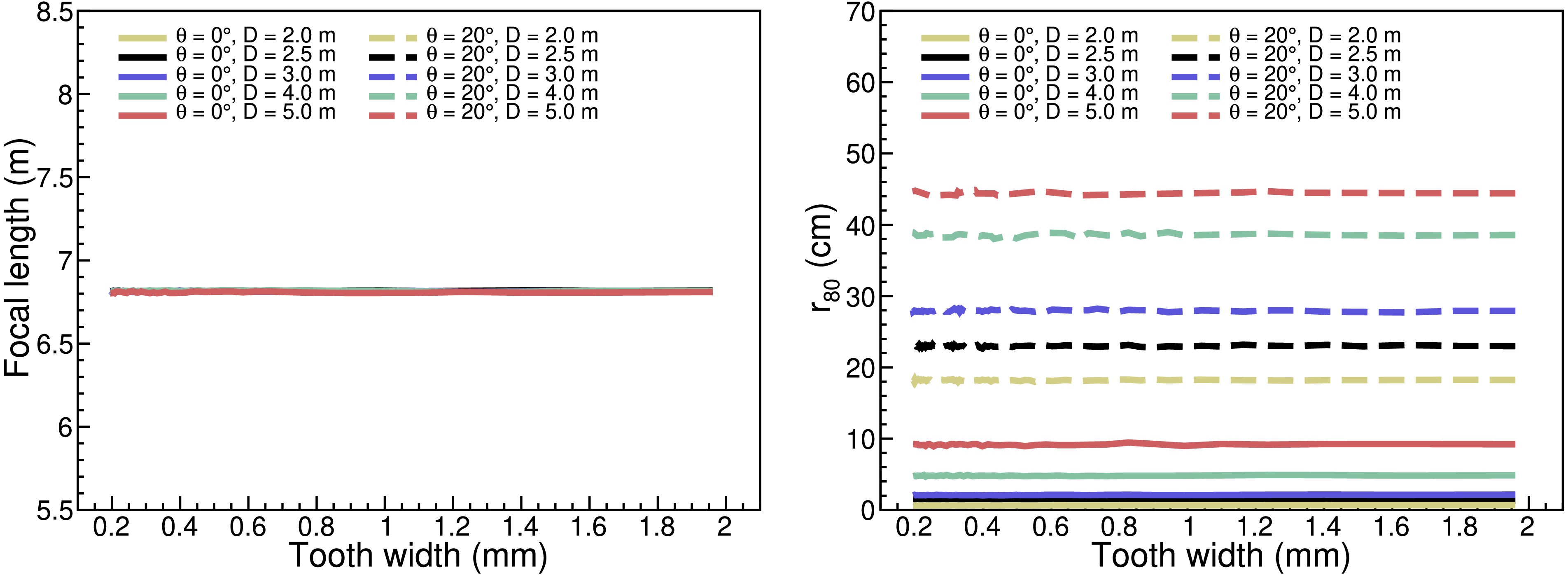
Figure 3. (color online) Effect of tooth width on focal length and
$r_{80}$ . Solid and dashed lines denote incident angles of 0° and 20°, respectively. The yellow, black, blue, green, and brownish-red curves correspond to Fresnel lenses with diameters of 2.0 m, 2.5 m, 3.0 m, 4.0 m, and 5.0 m, respectively.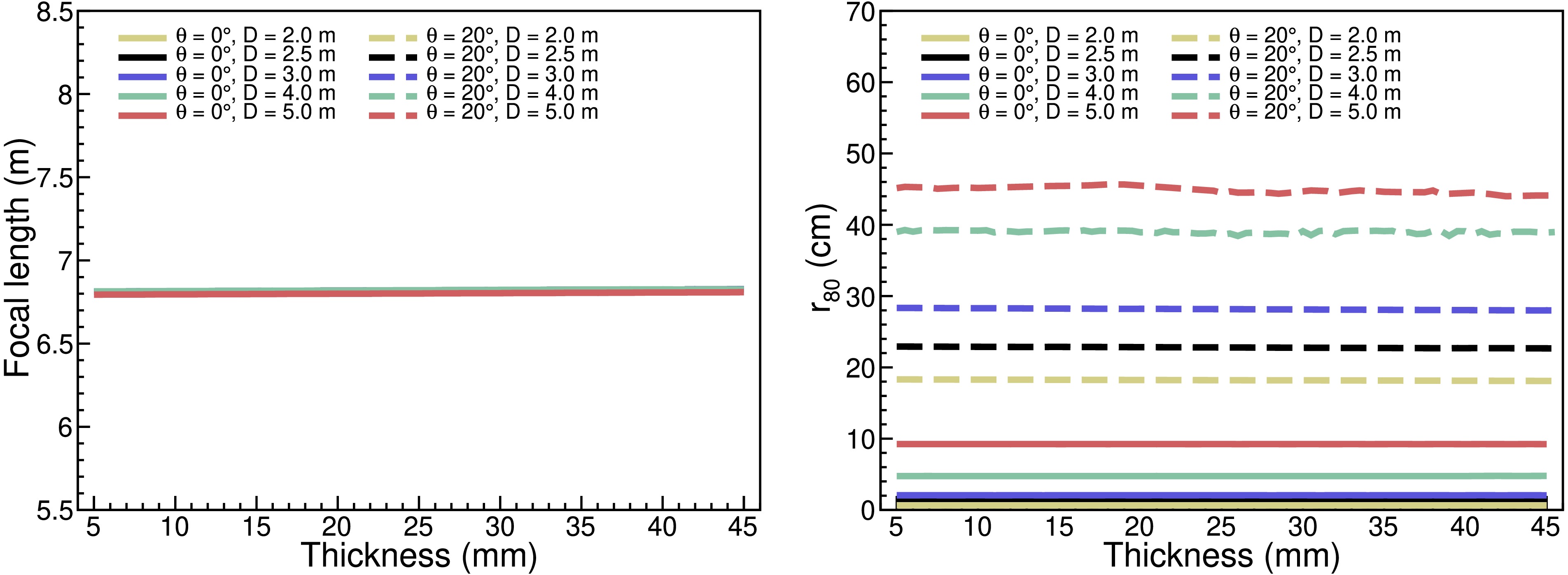
Figure 4. (color online) Effect of thickness on focal length and
$r_{80}$ . Solid and dashed lines denote incident angles of 0° and 20°, respectively. The yellow, black, blue, green, and brownish-red curves correspond to Fresnel lenses with diameters of 2.0 m, 2.5 m, 3.0 m, 4.0 m, and 5.0 m, respectively.Based on the influence of different parameters on focal length and
$r_{80}$ , we can draw the following conclusions:● The radius of curvature is the most important factor affecting the focal length and
$r_{80}$ . The tooth width and thickness of the Fresnel lens mainly affect the structural complexity of the lens, and have a smaller impact on the focal length and$r_{80}$ .● The focal length can be changed by altering the radius of curvature of the lens.
-
To facilitate subsequent comparisons with the 5.0 m diameter water lens in the HADAR project, the focal length of the Fresnel lens is set to be the same as that of the water lens: f = 6.8 m [4]. After simulation-based optimization, the design parameters for five diameter configurations of the Fresnel lens are compiled in Table 1.
Parameter Fresnel lens 1 Fresnel lens 2 Fresnel lens 3 Fresnel lens 4 Fresnel lens 5 Diameter (m) 2.0 2.5 3.0 4.0 5.0 Pitch ( $ ^\circ $ )0 0 2 0 0 Radius of curvature (m) 3.70 3.75 3.80 3.93 4.10 Tooth width (mm) 0.25 0.30 0.24 0.25 0.23 Thickness (mm) 10 10 15 10 30 Focal length (m) 6.8 6.8 6.8 6.8 6.8 $ r_{80} $ (cm)0.6 1.2 2.1 4.8 9.2 $ \theta_{80} $ ($ ^\circ $ )0.05 0.10 0.17 0.40 0.78 Table 1. Five configurations of Fresnel lenses.
-
The incident angle is defined as the angle between the incoming ray and the surface normal of the lens. The maximum allowable spot size in the experiment limits the incident angle, which corresponds to the FoV of the lens. The larger the incident angle that meets the requirements, the wider the FoV. Traditional Fresnel lenses generally adopt a planar image plane, but under wide FoV conditions, it is difficult for a plane to simultaneously meet the focusing requirements of rays at different incident angles, resulting in significant off-axis aberrations and an increase in
$r_{80}$ , which limits the imaging quality of the lens. Under different incident angles, there is a systematic shift in the focusing position, and the best focal length corresponding to the minimum$r_{80}$ changes with the incident angle. This indicates that the ideal image plane should adjust its curvature according to the incident angle, constructing a curved surface with gradually changing curvature to more accurately match the focusing depth of rays from different directions. We performed ray tracing within the incident angle range of 0-30°, extracted the location of the minimum$r_{80}$ , divided the central and edge parts into two sections, automatically determined the segmentation points based on minimizing the global root mean square error (RMSE), and fitted them with quadratic functions$ x = ay^2 + by + c $ (specific parameters are shown in Table 2) to obtain the image plane contour, as shown in Figure 5. Compared with planar and spherical surfaces, the variable curvature surface structure can achieve more precise focusing for rays at various angles, effectively reducing coma and improving imaging quality. We extracted the optimal focusing positions at different incident angles, rotated them around the optical axis to form a rotational surface, and calculated the image area corresponding to different diameter Fresnel lenses and the number of PMTs (Hamamatsu R11920-100 PMT) required for hexagonal close packing arrangement, as shown in Table 3.Diameter (m) Breakpoint N ( $ ^\circ $ )Central segment Edge segment a (mm $ ^{-1} $ )b c (mm) a (mm $ ^{-1} $ )b c (mm) 2.0 17 $ -2.10\times10^{-4} $ 0.000 6811.1 $ -4.53\times10^{-4} $ 0.911 5947.1 2.5 12 $ -1.98\times10^{-4} $ 0.000 6823.7 $ -3.53\times10^{-4} $ 0.454 6469.3 3.0 14 $ -1.96\times10^{-4} $ 0.000 6820.5 $ -3.53\times10^{-4} $ 0.479 6427.5 4.0 15 $ -1.87\times10^{-4} $ 0.000 6818.6 $ -2.65\times10^{-4} $ 0.093 6881.6 5.0 13 $ -1.75\times10^{-4} $ 0.000 6812.5 $ -3.88\times10^{-4} $ 0.666 6278.8 Table 2. Fitting parameters of image plane for Fresnel lenses with different diameters.
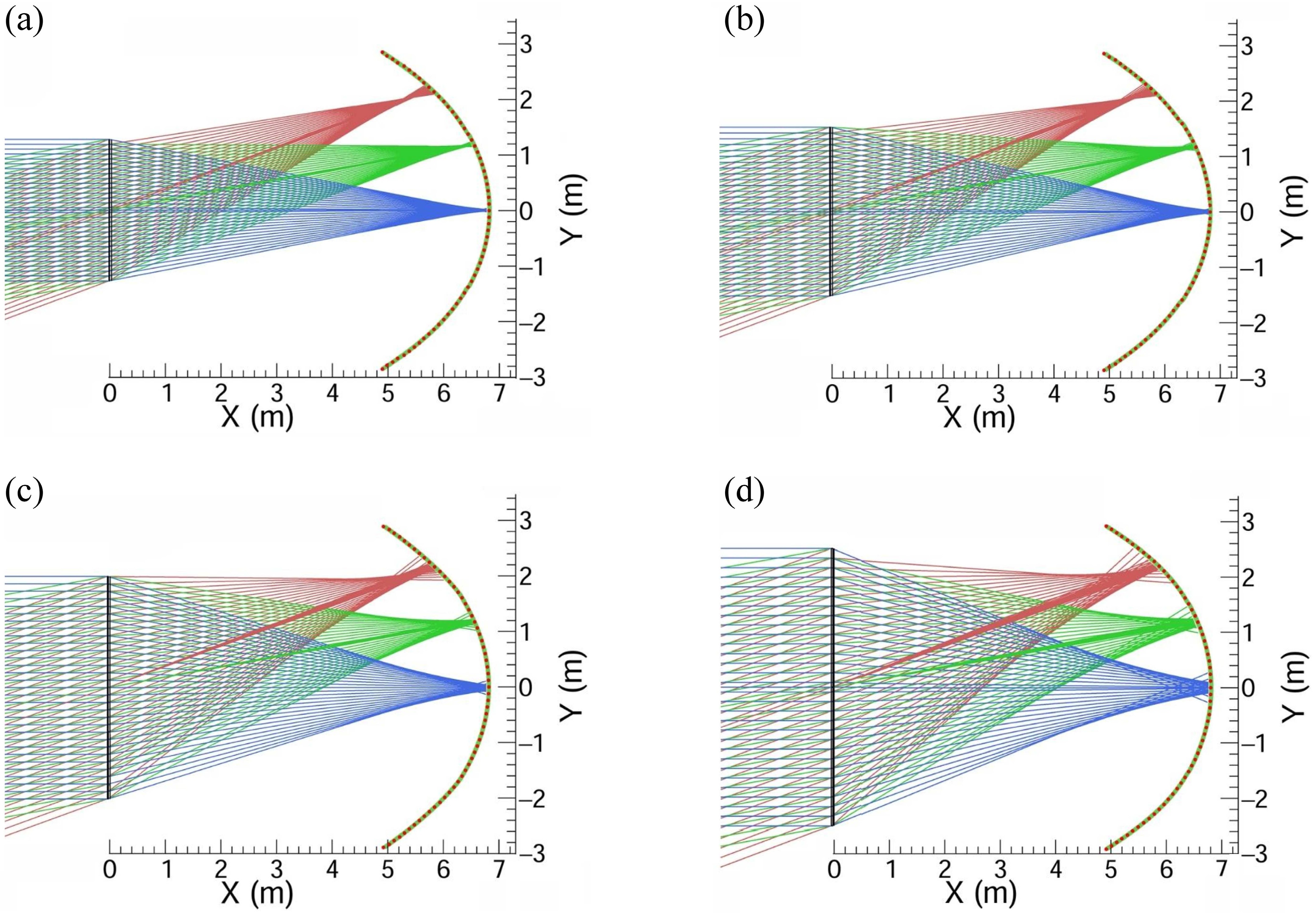
Figure 5. (color online) Ray-tracing schematic of the Fresnel lens. Panels (a)–(d) correspond to diameters of 2.5 m, 3.0 m, 4.0 m, and 5.0 m, respectively. The light-green curves are the image-surface profiles fitted with quadratic functions
$x = ay^2 + by + c$ , and the red dots mark the best-focus positions obtained from ray tracing. Blue, green, and red rays denote parallel incidence at 0°, 10°, and 20°, respectively. The Fresnel lens is located at X=0.Parameter Fresnel lens 1 Fresnel lens 2 Fresnel lens 3 Fresnel lens 4 Fresnel lens 5 Diameter (m) 2.0 2.5 3.0 4.0 5.0 Image height (m) 5.67 5.70 5.71 5.78 5.84 Image depth (m) 1.92 1.93 1.90 1.88 1.90 Total area of the image plane (m2) 35.61 35.84 35.73 36.16 37.30 Number of PMTs 16448 16554 16503 16702 17229 Table 3. Image area and PMT count for Fresnel lenses of different diameters.
-
$r_{80}$ , as an important indicator for measuring imaging quality, is sensitive to the incident angle of light, lens diameter, and focal length. Figure 6 presents$r_{80}$ versus incident angle for Fresnel lenses at different diameters and focal lengths, to assess wide FoV imaging performance (all simulations assume the curved image surface). At an incident angle of 0°, lenses with the same diameter but different focal lengths exhibit different$r_{80}$ ; moreover, a longer focal length leads to smaller spherical aberration and thus a smaller$r_{80}$ . As the incident angle increases, the$r_{80}$ of the lens becomes larger. For lenses with the same diameter but different focal lengths, when the incident angle is large (such as greater than 20°), the growth rate of$r_{80}$ tends to be consistent. At various incident angles, the$r_{80}$ of long focal length lenses is smaller than that of short focal length lenses. In geometrical optics, coma mainly arises from off-axis object points causing the magnification on the image side to vary with the aperture coordinate, resulting in inconsistent focusing of rays at different aperture positions on the image plane, forming a coma tail.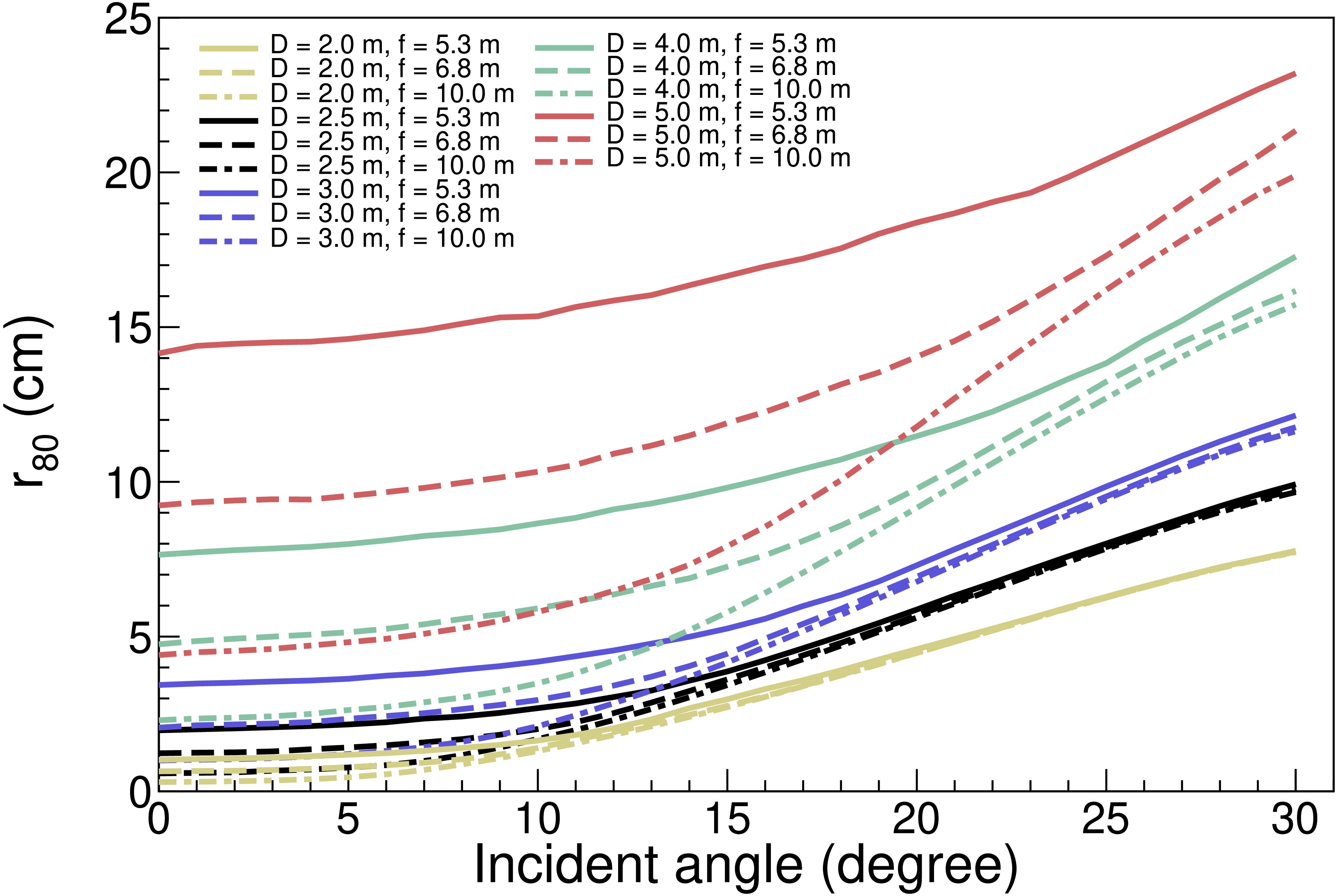
Figure 6. (color online) With a curved image surface,
$r_{80}$ versus incident angle for Fresnel lenses of different diameters and focal lengths. Colors denote diameter: yellow 2.0 m, black 2.5 m, blue 3.0 m, green 4.0 m, brownish-red 5.0 m. Line style denotes focal length: solid 5.3 m, dashed 6.8 m, dash-dotted 10.0 m.By applying the coma term in the wave aberration expansion [15] to the Fresnel lens, one finds that, for a fixed incident angle and diameter, the coma term scales approximately as
$f^{-2}$ . The longer the focal length, the smaller the coma. The$r_{80}$ of the long focal length lens is smaller than that of the short focal length lens. As the incident angle increases, the angular dependence of coma is almost entirely dominated by sinθ, and the focal length manifests as an overall amplitude factor. In comparisons with angle as the independent variable, coma curves for different focal lengths exhibit the same growth shape (only different amplitudes), manifested in that when the incident angle is large, the growth rate of$r_{80}$ tends to be consistent. Figure 7 shows the variation of$\theta_{80}$ with incident angle for different diameters and focal lengths.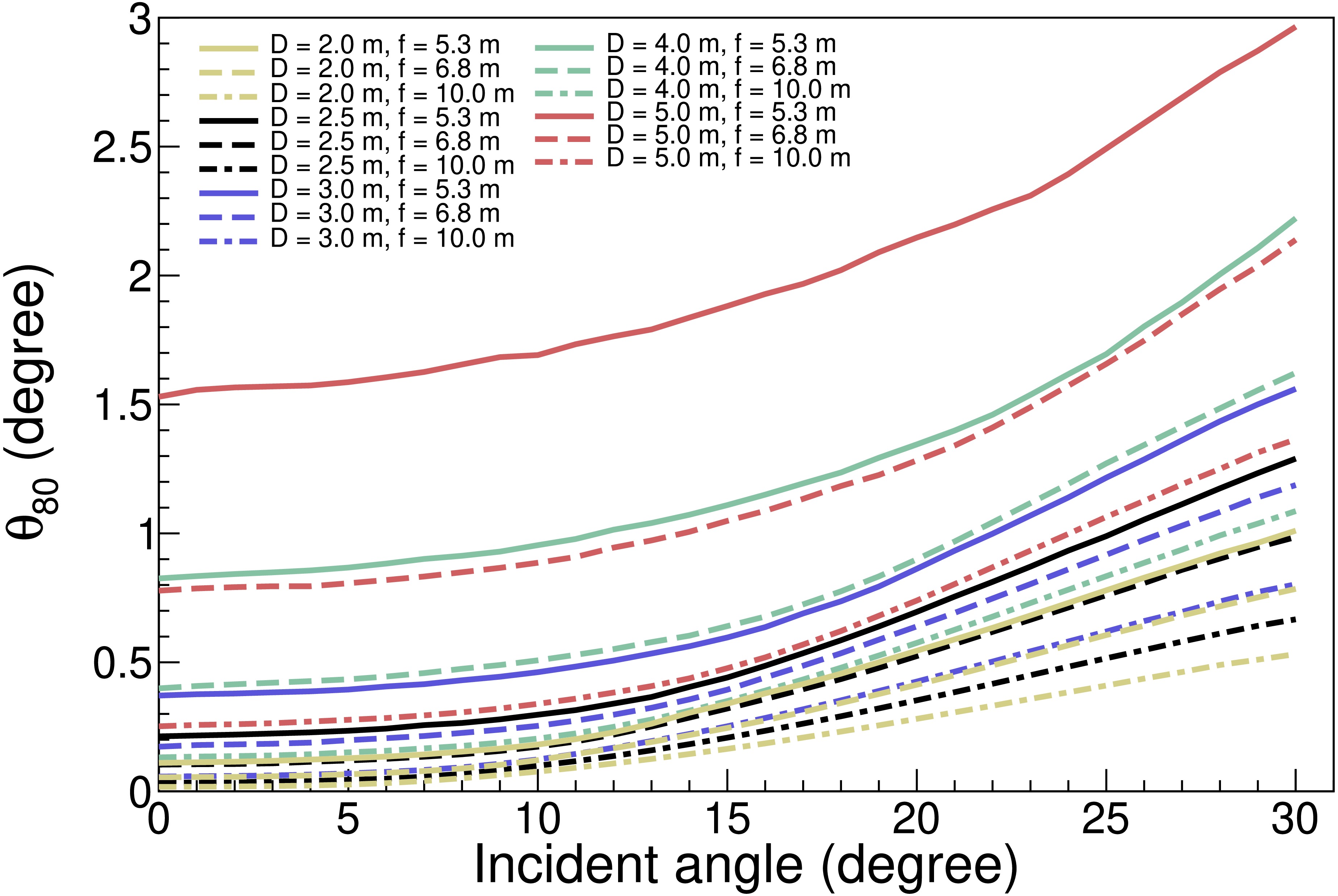
Figure 7. (color online) With a curved image surface,
$\theta_{80}$ versus incident angle for Fresnel lenses of different diameters and focal lengths. Colors denote diameter: yellow 2.0 m, black 2.5 m, blue 3.0 m, green 4.0 m, brownish-red 5.0 m. Line style denotes focal length: solid 5.3 m, dashed 6.8 m, dash-dotted 10.0 m.In summary, under the premise of fixed diameter and material, and paraxial imaging, the axial imaging quality is primarily controlled by spherical aberration. Increasing the focal length can reduce spherical aberration and improve the imaging quality in the central region. As the incident angle increases, the off-axis imaging quality is dominated by coma. The trend of
$r_{80}$ at different focal lengths deteriorating with the incident angle is basically the same, but the magnitude varies - for the same diameter,$r_{80}$ is smaller for longer focal lengths and larger for shorter focal lengths. Even with curved image surfaces, edge resolution is often limited by coma. -
Acceptance is a physical quantity that measures the system's ability to collect light from a certain direction, determined jointly by the geometric area of the receiving surface and the solid angle corresponding to that direction. The larger the acceptance, the lower the detection energy threshold can be in principle (evaluate geometric collection capability under the assumption of fixed incident rays quantity and ideal transmission, excluding material bulk absorption and surface reflection). Figure 8 shows the acceptance versus incident angle for Fresnel lenses at different diameters and focal lengths. As shown in Figure 8, the geometric area of the receiving surface increases with the square of the diameter. Lenses with larger diameters have higher acceptance at all incident angles compared to those with smaller diameters. Under the same diameter, an increase in focal length will cause the angle of the chief ray to the diameter to decrease, compress the effective solid angle, and reduce the acceptance. The image plane employs a curved surface, so that the chief ray at each field angle is nearly normal to the image surface. The photon flux is evenly distributed on the image plane, increasing the photon flux density when the incident angle is large, suppressing the change in the solid angle caused by the increase in the incident angle, and maintaining the stability of the acceptance at different incident angles. We use the size of PMT as a pixel, limiting the size of
$ r_{80} $ . The radius of a single PMT is 2.5 cm, and 7.5 cm is the radius of a circle with seven PMTs arranged in two circles. The total acceptance and FoV of Fresnel lenses with different diameters and focal lengths are compared as shown in Table 4. It can be found that increasing the diameter can enhance the photon flux, but narrows the FoV. To obtain a wider FoV, a longer focal length or a wider image quality threshold (the maximum allowable value of$ r_{80} $ ) is required. Large-diameter Fresnel lenses: they have more effective photons collection per unit FoV and lower energy threshold, but have a narrower FoV, longer focal length, and higher construction costs. Small-diameter Fresnel lenses: they have a wider FoV, a more compact system, and lower cost, but have a smaller acceptance. The selection should be based on a trade-off between energy threshold and FoV according to scientific objectives.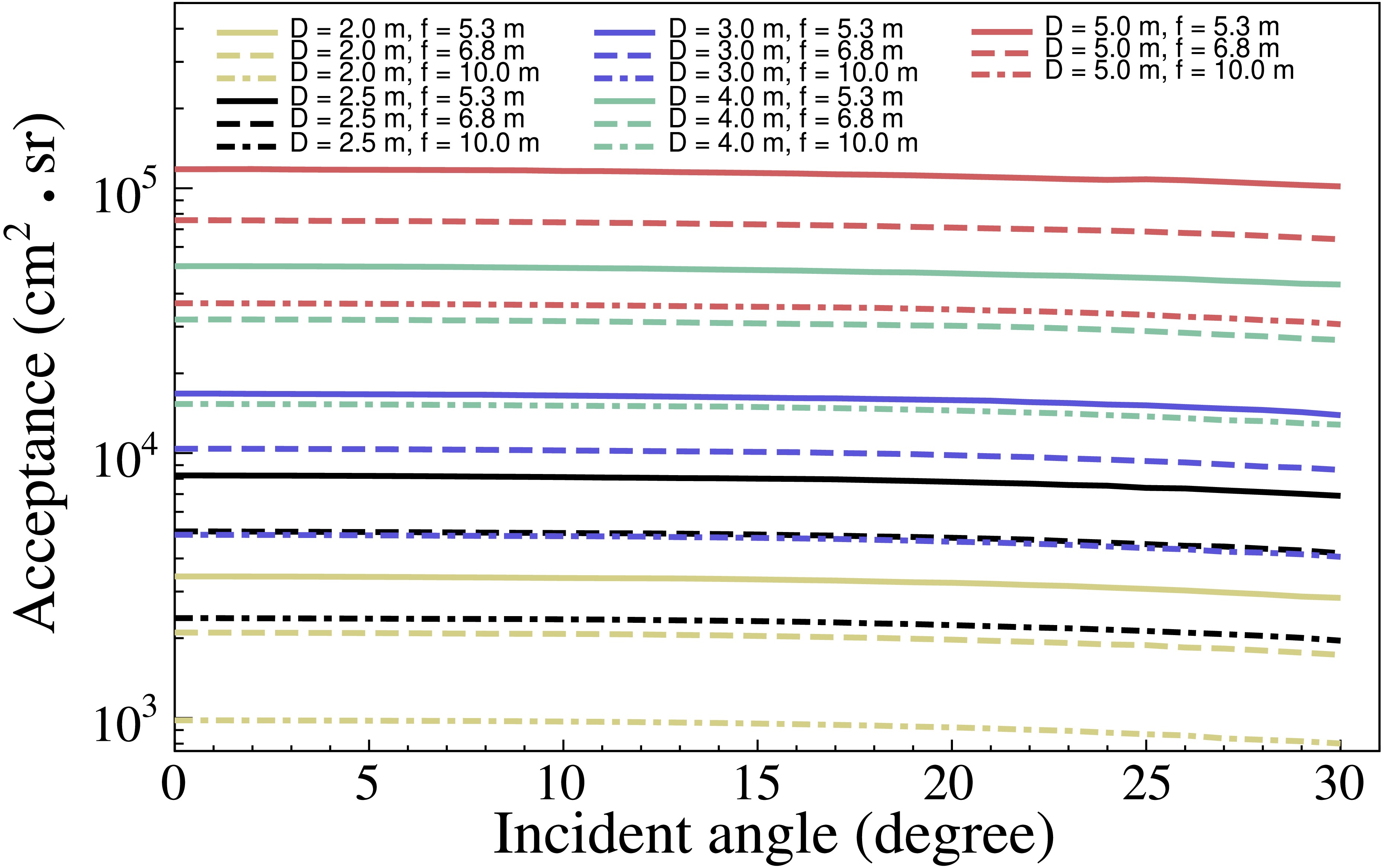
Figure 8. (color online) With a curved image surface, acceptance versus incident angle for Fresnel lenses of different diameters and focal lengths. Colors denote diameter: yellow 2.0 m, black 2.5 m, blue 3.0 m, green 4.0 m, brownish-red 5.0 m. Line style denotes focal length: solid 5.3 m, dashed 6.8 m, dash-dotted 10.0 m.
Diameter
(m)Focal
length (m)$ r_{80} $ <2.5 cm$ r_{80} $ <7.5 cmTotal
acceptance
(m2·sr)FoV (sr) Total
acceptance
(m2·sr)FoV (sr) 2.0 5.3 4.75 0.16 9.81 0.79 6.8 3.12 0.19 6.01 0.79 10.0 1.46 0.19 2.80 0.79 2.5 5.3 7.38 0.06 19.27 0.50 6.8 6.03 0.12 12.31 0.54 10.0 3.08 0.14 5.79 0.54 3.0 5.3 — — 34.48 0.38 6.8 7.25 0.03 22.39 0.42 10.0 5.86 0.12 10.60 0.42 4.0 5.3 — — — — 6.8 — — 50.53 0.21 10.0 7.65 0.02 27.23 0.27 5.0 5.3 — — — — 6.8 — — — — 10.0 — — 54.59 0.19 Table 4. Total acceptance and FoV of the Fresnel lens for different diameters and focal lengths.
-
Considering the performance and cost of the Fresnel lens, the basic selection criteria for a single lens are set as follows:
$ r_{80} $ $ \lt $ 7.5 cm for on-axis imaging (θ = 0°). This requirement limits 80% of the on-axis photon energy to a local cluster consisting of seven PMTs, thereby reducing cross-pixel crosstalk and enhancing the reliability of triggering and reconstruction. If higher imaging quality is required, a stricter criterion of$ r_{80} $ $ \lt $ 2.5 cm can be adopted. Table 5 presents the minimum focal lengths (at an incident angle of 0°) corresponding to different diameters under the conditions of$ r_{80} $ $ \lt $ 2.5 cm and$ r_{80} $ $ \lt $ 7.5 cm. Considering that$ r_{80} $ increases with the incident angle, to ensure that$ r_{80} $ $ \lt $ 2.5 cm or$ \lt $ 7.5 cm is still met at the maximum incident angle of the target, the actual focal length selected should be greater than the values given in the table. Therefore, the data in the table serves only as a lower limit benchmark for selection, and the final focal length needs to be appropriately increased in conjunction with the target FoV. The HADAR project limits the focal length of the lens used to within 10.0 m. When$ r_{80} $ $ \lt $ 7.5 cm, the$ \theta_{80} $ under the maximum incidence angle, FoV, and total acceptance will be used as comprehensive selection criteria, as shown in Table 6.Diameter
(m)$ r_{80}<2.5 $ cm, focal
length (m)$ r_{80}<7.5 $ cm, focal
length (m)2.0 3.4 1.8 2.5 4.7 2.6 3.0 6.3 3.5 4.0 9.8 5.4 5.0 13.6 7.6 Table 5. Minimum focal length for Fresnel lenses of different diameters under the
$ r_{80} $ constraint.Diameter
(m)Focal length
(m)$ \boldsymbol{\theta_{80}} $
($ ^\circ $ )FoV
($ ^\circ $ )Total acceptance
(m2·sr)2.0 5.3 0.96 29 9.81 2.5 6.8 0.71 24 12.31 3.0 10 0.46 21 10.6 4.0 10 0.43 17 27.23 5.0 10 0.44 14 54.59 Table 6. Parameters for Fresnel lenses of different diameters under constraints on focal length and
$ r_{80} $ .To meet the scientific objectives of this study aligned with HADAR (wide FoV for transient/extended sources and as low-energy threshold as possible) while considering engineering constraints (focal length
$ \leq $ 10.0 m), we selected Fresnel lens parameters with total acceptance not less than that of the water lens (7.43 m2·sr), on-axis imaging$ r_{80} $ $ \lt $ 7.5 cm. While maintaining acceptance above the water lens level to enhance the FoV, we chose D = 2.0 m, f = 5.3 m for the Fresnel lens, achieving an FoV angle of 29° and total acceptance of 9.81 m2·sr. Based on this, we recommend the Fresnel lens with a diameter of 2.0 m and a focal length of 5.3 m as the benchmark for the detection unit in HADAR array performance simulation. -
This paper conducted simulations on the basic optical performance of the Fresnel lens targeting the physical objectives of the HADAR project. The results indicate that the Fresnel lens can serve as a viable alternative to the water lens within the HADAR project. The radius of curvature of the Fresnel lens is the largest factor affecting the focal length and the size of the image spot (
$ r_{80} $ ). The focal length increases with the increase of the radius of curvature, while$ r_{80} $ decreases with the increase of the radius of curvature until it remains unchanged. The tooth width and thickness of the lens have a minor impact on the focal length and$ r_{80} $ , mainly affecting the complexity of the Fresnel lens structure. Based on this, five Fresnel lenses with diameters of 2.0 m, 2.5 m, 3.0 m, 4.0 m, and 5.0 m, respectively, were designed to have the same focal length as the water lens. We extracted the optimal focusing positions under different incident angles and fitted the curved image surface with gradually varying curvature. This significantly improved the imaging quality and suppressed the change in solid angle caused by the increase in incident angle, maintaining the stability of acceptance at different incident angles. Large-diameter Fresnel lenses have greater acceptance and lower energy threshold, but they have a longer focal length, narrower FoV, and higher construction costs; small-diameter Fresnel lenses have a wider FoV, a more compact system, and lower construction costs, but their acceptance is relatively small.Considering the performance and cost of the Fresnel lens, the basic selection criteria for a single lens are set as follows:
$ r_{80} $ $ \lt $ 7.5 cm when imaging on-axis (θ = 0°). The HADAR project limits the telescope focal length to$ \leq $ 10.0 m. When$ r_{80} $ $ \lt $ 7.5 cm, we adopt the principle of maintaining a total acceptance no less than that of the water lens unit (7.43 m2·sr) while maximizing the FoV, and accordingly select a Fresnel lens with a diameter of 2.0 m and a focal length of 5.3 m (FoV angle 29°, total acceptance 9.81 m2·sr) as the baseline lens unit specification for subsequent array simulations. The Fresnel lens has a mature manufacturing process, low maintenance costs, and strong adaptability at high altitudes and low temperatures, making it an alternative solution for the detection unit of the HADAR project.
The HADAR Project Based on Fresnel Lenses, Part I: Optical Simulation Study of the Telescope Unit
- Received Date: 2025-07-07
- Available Online: 2026-05-01
Abstract: The High Altitude Detection of Astronomical Radiation (HADAR) project proposes the use of a refracting telescope composed of four 5.0 m diameter water lenses arranged in a square configuration (100 m × 100 m), featuring a wide field of view (FoV, up to 0.84 sr) and low-energy threshold characteristics, to observe Cherenkov light generated by high-energy cosmic rays in atmospheric air showers. The Fresnel lens exhibits excellent imaging performance, lightweight characteristics, mature manufacturing processes, strong adaptability in high-altitude low-temperature environments, and facilitates array deployment. It has been engineering-validated through a series of pilot missions in the JEM-EUSO program, leading to the proposal of a telescope unit design that utilizes the Fresnel lens as an alternative to the water lens. This paper simulates and examines the influence of parameters such as the radius of curvature, tooth width, and thickness of the Fresnel lens on the focal length and image spot ($r_{80}$). Five Fresnel lenses with the same focal length as the 5.0 m diameter water lens are designed. The best focusing positions under different incident angles were extracted, and the curved image surface was constructed through fitting. The results show that the imaging quality of the Fresnel lens mainly depends on the radius of curvature. As the focal length increases, $r_{80}$ gradually decreases until it remains unchanged. The tooth width and thickness of the lens mainly affect the structural complexity of the lens and have little impact on the imaging quality. The curved image surface design can effectively suppress the aberrations and changes in solid angle caused by increased incidence angles, thereby maintaining the acceptance approximately consistent across different incidence angles. To meet the scientific objectives (wide FoV, low-energy threshold) consistent with HADAR and take into account engineering constraints (focal length $\leq$ 10 m) in this paper, we select a Fresnel lens with a diameter of 2.0 m and a focal length of 5.3 m (FoV angle 29°, total acceptance 9.81 m2·sr) as the basic lens unit for subsequent array performance simulation, based on the premise that the total acceptance is not lower than that of the water lens unit (7.43 m2·sr), the on-axis imaging $r_{80}$ is less than 7.5 cm, and the FoV is as wide as possible.


 DownLoad: