


 Abstract
 HTML
HTML Reference
 Related
 PDF
PDF


-
Mass is a fundamental physical quantity of atomic nuclei; in particular, the masses of neutron-rich nuclei far from stability are important for understanding the path of nucleosynthesis for heavy elements. The Rare-RI Ring (R3) constructed at the RIKEN RI beam factory is a storage ring dedicated to the precise mass measurements of short-lived rare RIs. Details of the R3 are given in Refs. [1, 2]. The principle of the mass measurements at the R3 is based on isochronous mass spectrometry. The revolution time (T) of a nucleus of interest in the R3 should be corrected by the velocity (β) of the nucleus because the isochronous condition of the R3 is tuned to a reference nucleus. To obtain β and T, three time-of-flight (TOF) detectors are used for mass measurements at the R3; the first and second TOF detectors are installed upstream of the R3, and the third is downstream. The second detector is used as both the stop detector of the TOF measurement for β and the start one of the TOF measurement for T. To achieve a mass precision of
$ 10^{-6} $ , the time resolution of TOF detectors must be less than 100 ps, and the detection efficiency is preferably close to 100%. In addition, the second TOF detector requires the thinnest possible material to minimize changes in ion velocity.To satisfy the above requirements, we developed a TOF detector utilizing a thin foil and crossed static electric and magnetic fields, called the BE-MCP [3, 4]. In the previous study [3], a reduction of the detection efficiency around the left and right edges on the foil was reported. Also, the operation of the previous BE-MCP was unstable due to electric discharge. This issue must be solved for long-term operation during mass measurements. Figure 1(a) shows a schematic view of the BE-MCP. Of the three electrodes, the inner electrode is fitted with aluminum-coated Mylar (1 μm thick) as the thin foil, and the two outer electrodes are equipped with holes for entrance and exit as the ions pass through. The polarity of the potentials for the inner and outer electrodes is negative and positive, respectively. The magnetic field is produced by arranging several pieces of neodymium permanent magnets, and the strength can be changed by varying the number of magnet pieces. Secondary electrons are generated as the ions pass through the thin foil; they are isochronously transported to two microchannel plate (MCP) detectors by crossed static electric and magnetic fields. TOF detectors of the same type as the BE-MCP are installed in the experimental cooler-storage ring (CSRe) at IMP and the experimental storage ring (ESR) at GSI [5−7]. These TOF detectors measure the turn-by-turn TOF of ions circulating in these storage rings. In the present study, we modified the BE-MCP to increase the good efficiency region on the foil and prevent discharge.
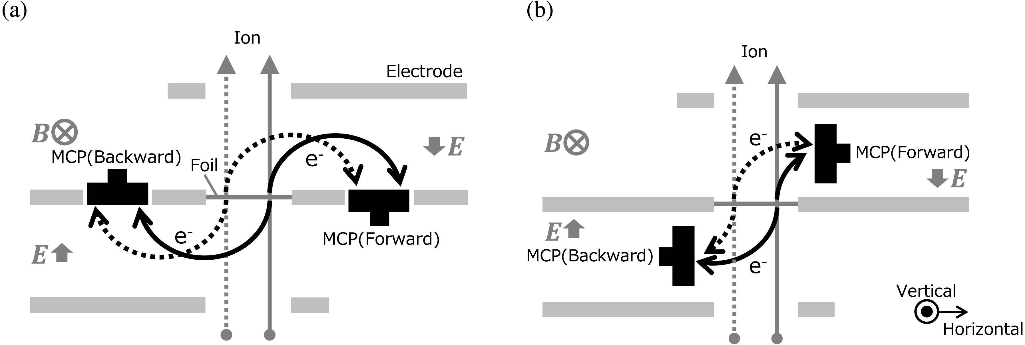
Figure 1. Schematic view of (a) BE-MCP and (b) BE-MCP90. E and B represent static electric and magnetic fields, respectively. MCP and
$ \rm{e^{-}} $ represent a microchannel plate detector and secondary electrons, respectively.We also developed a position-sensitive detector based on the BE-MCP, called the BE-MCP90. Figure 1 (b) shows a schematic view of the BE-MCP90. Unlike the BE-MCP, two MCP detectors of the BE-MCP90 are located in the gap of electrodes, and the effective area of the MCP is orthogonal to the electrodes. Through this arrangement, a difference in the transport time of electrons emitted forward and backward from the foil is sensitive to the horizontal position of the ions passing through the foil. In a previous study, this position sensitivity of the BE-MCP90 was experimentally confirmed [4]. In the present study, we enlarged the vertical acceptance by using large MCP detectors compared to those of the prototype.
-
In the present study, we modified the electrodes of the BE-MCP. The inner electrode of the BE-MCP has two holes where the MCP detectors are mounted in an electrically floating configuration. The diameter of these holes was changed from 78 to 82 mm to prevent electric discharge between the MCP and electrode. According to Ref. [3], these holes have almost no effect on the electric field along the path of secondary electrons. The gap between the inner and outer electrodes was changed from 34 to 38 mm to transport secondary electrons using a more homogeneous electric field. As the gap between the electrodes increases, the uniformity of the electric field is enhanced [3]. Reducing the electric field due to the voltages applied to the inner (
$ V_{\rm i} $ ) and outer ($ V_{\rm o} $ ) electrodes and magnetic field is also effective for preventing electric discharges. In the present study, we reduced the electric field from 547 V/mm ($ V_{\rm i} = -4.0 $ kV,$ V_{\rm o} = +14.6 $ kV) to 342 V/mm ($ V_{\rm i} = -6.0 $ kV,$ V_{\rm o} = +7.0 $ kV) and the magnetic field from 0.0150 to 0.0117 T. Increasing the negative potential causes secondary electrons to focus along the horizontal axis. This improves the detection efficiency. Besides these changes, the design of the BE-MCP is almost the same as that of the previous one [3].An online test of the current BE-MCP was performed using
$ ^{84} $ Kr ion beams of 200 MeV/nucleon provided by the Heavy Ion Medical Accelerator in Chiba (HIMAC). In this case, a relative change of velocity as ions pass through the thin foil (Mylar, 1 μm thick) is calculated to be$ \delta\beta/\beta \sim -2 \times 10^{\rm {-5}} $ , and this change is acceptable for mass measurements at the R3. The typical beam intensity was$ \sim1\times 10^3 $ particles per second. Several defocused beams shifted along the horizontal and vertical axes were used to irradiate the entire area of the foil. The experimental setup shown in Fig. 2 was almost the same as the previous one [3]. The plastic scintillation counter was used as a trigger detector for the data acquisition and TOF start. Two parallel plate avalanche counters (PPACs) [8], which are position-sensitive gas detectors, were placed upstream and downstream of the vacuum chamber for beam tracking. The BE-MCP was installed in the vacuum chamber with entrance and exit windows (Mylar, 100 μm thick), and the signals of the two MCP detectors were used for the TOF stop. A thallium-doped sodium iodide (NaI(Tl)) scintillation counter was used for the event selection for ions passing through the foil. The distances from the foil of the BE-MCP to the plastic scintillation counter and the entrance of the NaI(Tl) were$ \sim $ 1000 mm and$ \sim $ 560 mm, respectively.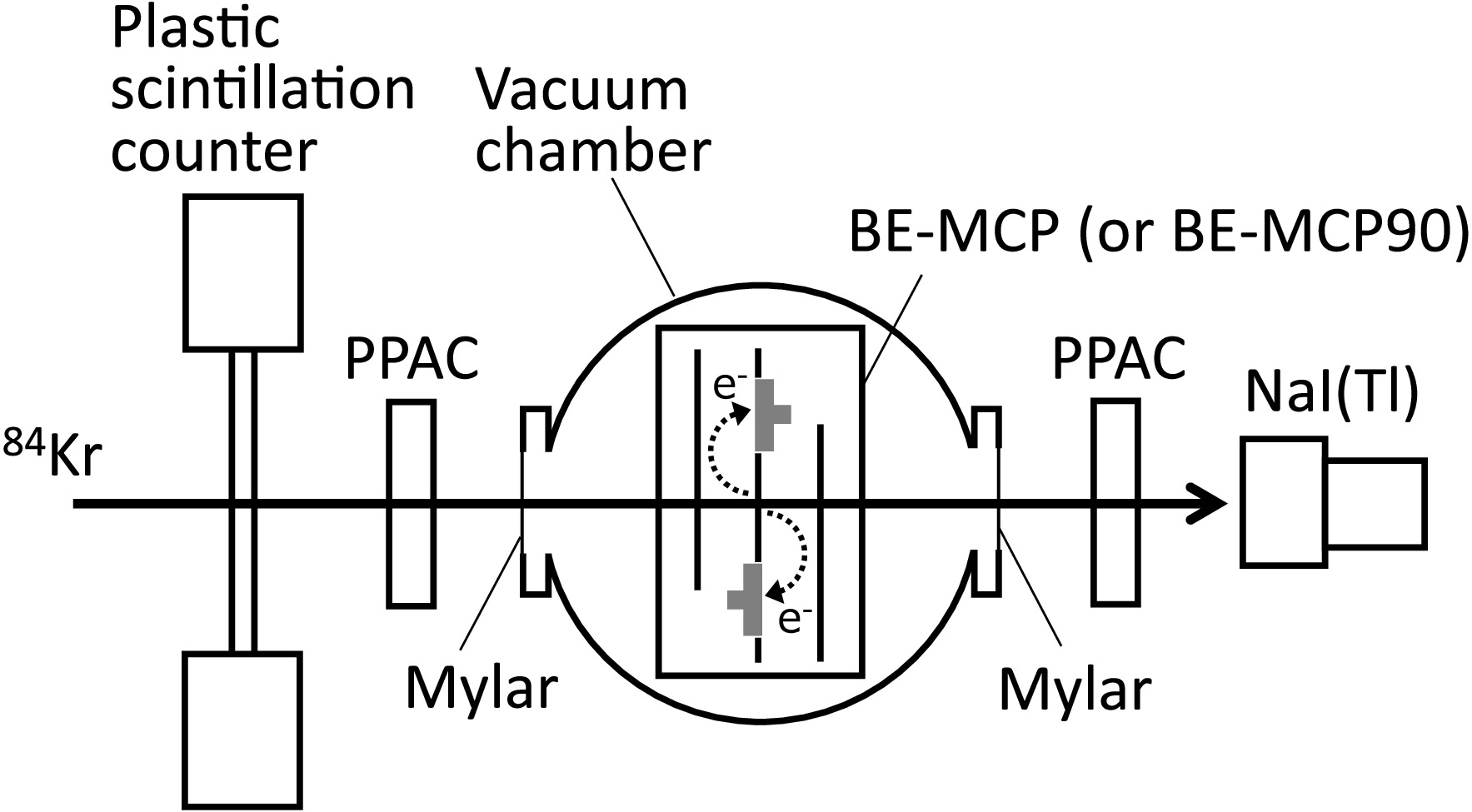
Figure 2. Schematic view of the experimental setup. PPAC and NaI(Tl) represent parallel plate avalanche and thallium-doped sodium iodide scintillation counters, respectively. The BE-MCP in the vacuum chamber was replaced with the BE-MCP90 for the online test of the latter.
Figure 3 (a) shows a typical time spectrum of the BE-MCP, which is an average of the TOFs obtained by the forward and backward MCP detectors. A time resolution of 45 ps in standard deviation (σ) was obtained by a Gaussian fit to the peak, as shown in Fig. 3 (a). The intrinsic time resolution was obtained as
$ \sigma\sim $ 40 ps, by subtracting those of the trigger timing and electronics. This resolution is sufficient for mass measurements at the R3 as well as the previous result ($ \sigma=38.6(2) $ ps [3]). The present modifications do not significantly affect the time resolution of the BE-MCP. Figure 3 (b) shows the position dependence of the detection efficiency on the foil. The detection efficiency was defined as the ratio of the number of coincidences between the forward and backward detections divided by the number of ions passing through the foil. As shown in Fig. 3(b), a good efficiency was obtained over the entire foil, and the average efficiency was 92.5(2)% within a diameter of 40 mm on the foil. For the present BE-MCP, a stable operation for more than a week was accomplished without electric discharge. Therefore, we finalized the design and specification of the BE-MCP. The BE-MCP was installed upstream of the R3 as the second TOF detector and was used for mass measurements. In Ref. [9], we successfully confirmed the extraction of five nuclides, including$ ^{74} $ Ni, from the R3, and data analysis is ongoing. Note that the data from Ref. [9] are preliminary; final results will be published in a peer-reviewed journal.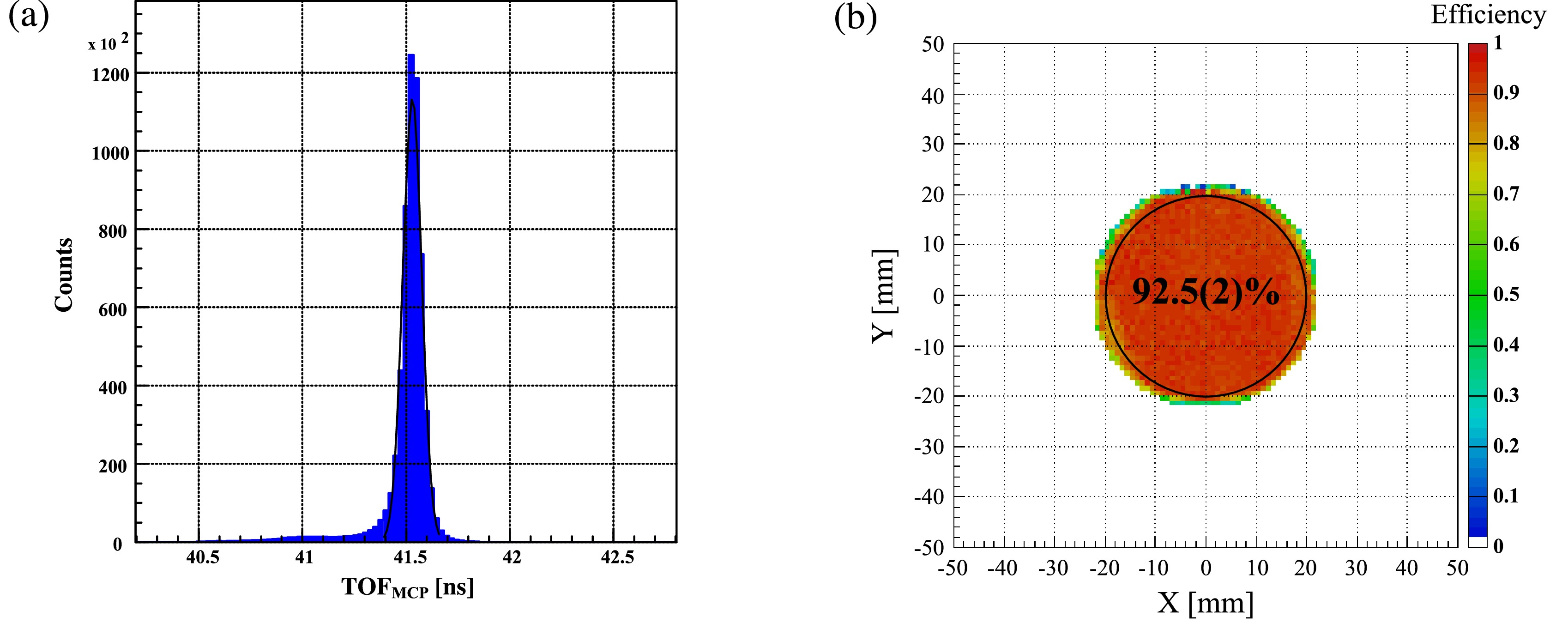
Figure 3. (color online) (a) Typical time spectrum of the BE-MCP for ions passing through the entire 45-mm-diameter foil. The solid line indicates the best fit using a Gaussian function. The time resolution of the BE-MCP was obtained within standard deviation σ
$ \sim $ 45 ps. (b) Position dependence of the detection efficiency on the foil. X and Y indicate the horizontal and vertical positions on the foil, respectively. The detection efficiency was 92.5(2)% within the 40-mm-diameter area surrounded by the solid line. -
The vertical acceptance of the prototype BE-MCP90 was limited to within approximately
$ \pm7.5 $ mm due to the effective area of the MCP detectors ($ \phi15 $ mm). In the present study, to improve the vertical acceptance, we used large MCP detectors with an effective area of$ \phi42 $ mm, which is almost the same as that of the foil. The inner electrode was modified to mount large MCP detectors, as shown in Fig. 4, and the gap between the inner and outer electrodes was increased to 73 mm. An online test of the current BE-MCP90 was performed using$ ^{84} $ Kr ions of 200 MeV/nucleon at HIMAC. The experimental setup is shown in Fig. 2, but the BE-MCP in the vacuum chamber was replaced with the BE-MCP90. Figure 5 shows the position dependence of the detection efficiency on the foil in different magnetic fields. The definition of the detection efficiency is the same as that in Fig. 3 (b). For each magnetic field, the potential of the inner electrode was fixed to −6 kV, and that of the outer electrodes was optimized to maximize the efficient region. As shown in Fig. 5, good efficiency was obtained over the entire foil under a magnetic field of 0.072 T. Increasing the electric and magnetic fields reduced the positional scattering of the secondary electrons on the vertical axis. The difference in the detection time for secondary electrons between forward and backward MCP detectors was sensitive to the horizontal position on the foil, as shown in Fig. 6 (a). By fitting this correlation with a linear function, the time difference of the MCP detectors could be converted to a position ($ \rm{X}_{\rm{MCP}} $ ), as shown in Fig. 6 (b). Figure 7 (a) shows the position resolution (σ) obtained by a Gaussian fit to the peak of the$ \rm{X}_{\rm{MCP}} $ axis with events selected every 1 mm along the$ \rm{X}_{\rm{PPAC}} $ axis. The average position resolution was$ \sigma\sim $ 1.5 mm, but the resolution around the center was better than that of the outside. This position dependence of the resolution is likely due to the deviation of the stop time for the MCP detector at the far side, because the deviation of the transport time of the secondary electrons increases with the transport length of these electrons. The position dependence was not significant along the vertical axis. The tracking uncertainty of the PPACs was estimated to be 0.6 mm [8], but this value does not significantly affect the position resolution of the BE-MCP90. As shown in Fig. 7 (b), the average position resolution on the horizontal axis was almost constant as the magnetic field varied. In the present study, a magnetic field of 0.072 T was desirable for the operation of the BE-MCP90 in terms of detection efficiency. The energy loss of$ ^{84} $ Kr ions at 200 MeV/nucleon was calculated to be approximately 200 MeV for the PPAC. In contrast, the energy loss at the BE-MCP90 was estimated to be approximately 1 MeV, which is less than$ 10^{-4} $ of the total energy of the$ ^{84} $ Kr ions, as the foil material was only 1-μm-thick Mylar. Therefore, in comparison with the PPAC, we successfully developed a position-sensitive detector with very low material thickness.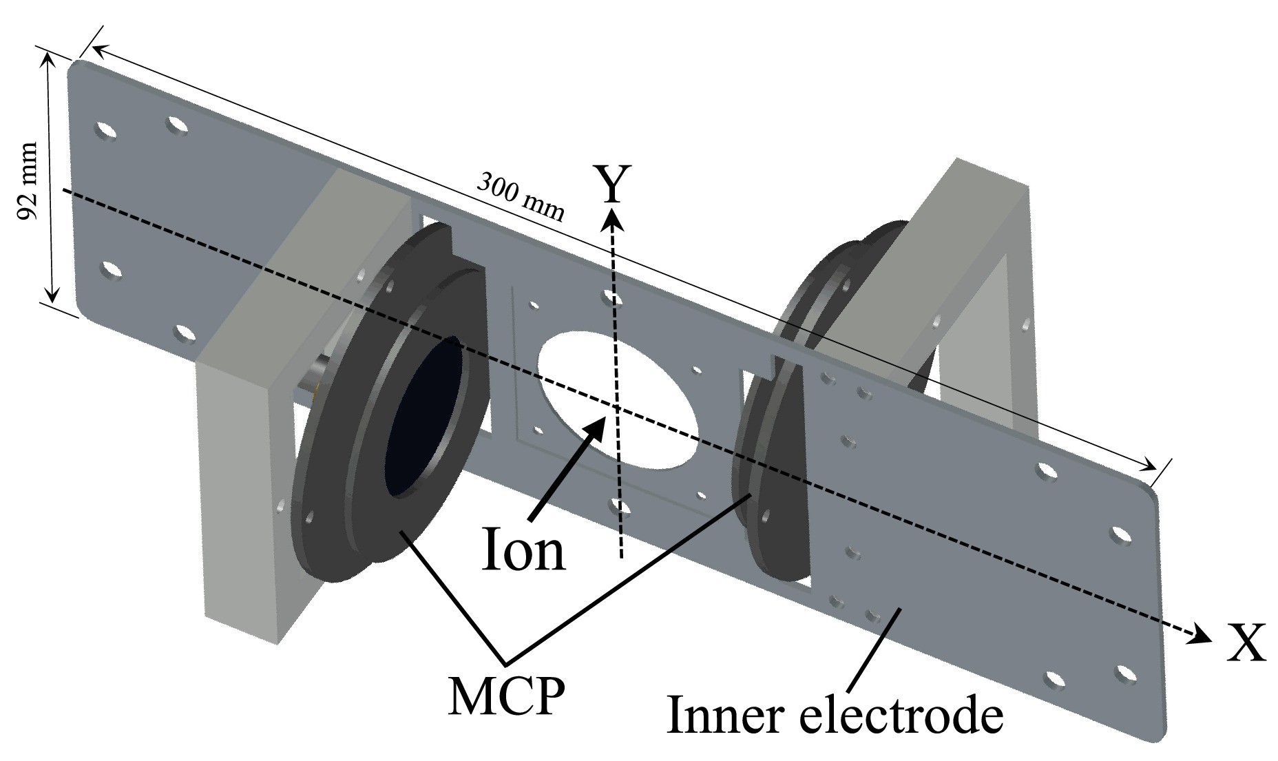
Figure 4. Inner electrode attached to microchannel plate (MCP) detectors for the current BE-MCP90. In the present study, the inner electrode was modified to attach large MCPs. A thin foil for the production of secondary electrons was attached to the center hole of the inner electrode. X and Y indicate the horizontal and vertical axes, respectively.
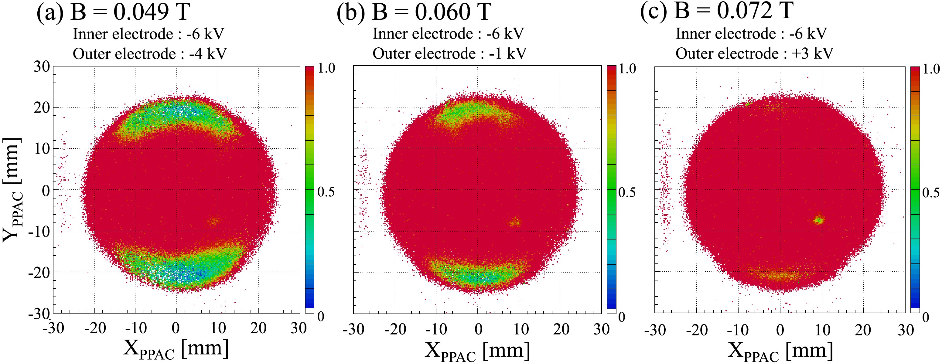
Figure 5. (color online) Position dependence of the detection efficiency of the BE-MCP90 for magnetic fields of (a) 0.049 T, (b) 0.060 T, and (c) 0.072 T. The efficiency is color coded.
$ \rm{X}_{\rm {PPAC}} $ and$ \rm{Y}_{\rm {PPAC}} $ were obtained from the tracking of two PPACs. The detection efficiency on the upper and lower sides was improved by increasing the electric and magnetic fields.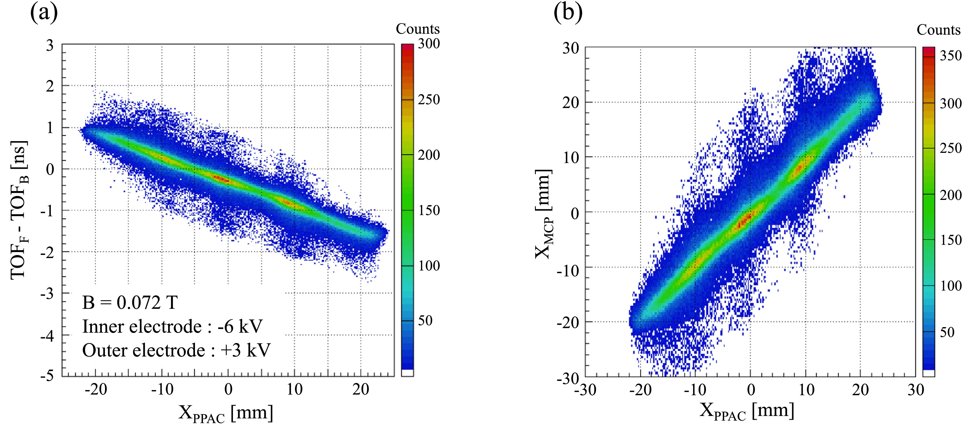
Figure 6. (color online) (a) Time difference between forward and backward MCP detectors (
$ \rm{TOF_{\rm F}} $ -$ \rm{TOF_{\rm B}} $ ) as a function of horizontal position on the foil ($ \rm{X}_{\rm{PPAC}} $ ), obtained from the tracking of PPACs. A clear correlation was observed between$ \rm{X}_{\rm{PPAC}} $ and$ \rm{TOF_{\rm F}} $ -$ \rm{TOF_{\rm B}} $ . (b) Horizontal position obtained from BE-MCP90 ($ \rm{X}_{\rm{MCP}} $ ) as a function of$ \rm{X}_{\rm{PPAC}} $ .$ \rm{X}_{\rm{MCP}} $ was converted from the correlation between$ \rm{X}_{\rm{PPAC}} $ and$ \rm{TOF_{\rm F}} $ -$ \rm{TOF_{\rm B}} $ .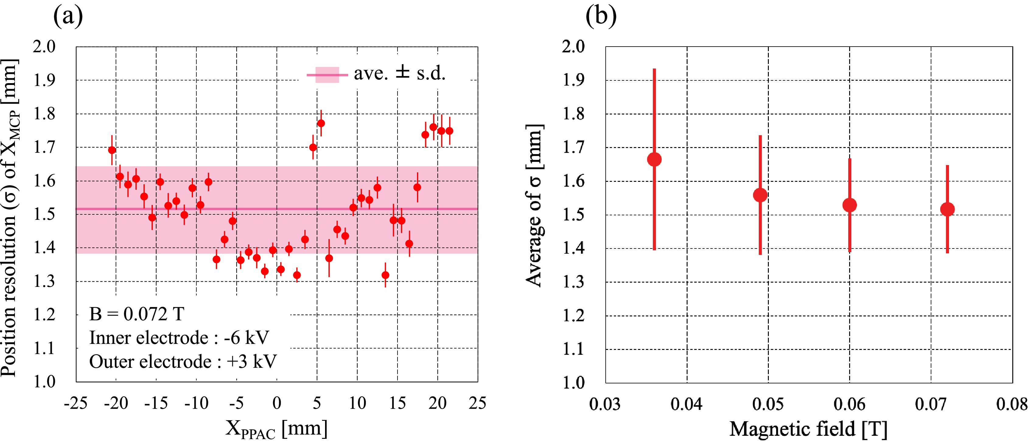
Figure 7. (color online) (a) Position resolution (σ) of
$ \rm{X}_{\rm{MCP}} $ along the horizontal axis. The solid line and band indicate the average and standard deviation, respectively. The average position resolution is$ \sigma\sim $ 1.5 mm in a magnetic field of 0.072 T. (b) Average position resolution of the$ \rm{X}_{\rm{MCP}} $ as a function of the magnetic field. The position resolution of$ \rm{X}_{\rm{MCP}} $ is almost constant even though the magnetic field is varied. -
We developed a time-of-flight detector utilizing a thin foil with crossed static electric and magnetic fields, called the BE-MCP, for mass measurements at the R3. Secondary electrons emitted forward and backward from the foil that ions pass through were detected by two microchannel plate (MCP) detectors. Through the present improvements, the intrinsic time resolution was typically
$ \sim $ 40 ps for the entire foil in a performance test using$ ^{\rm 84} $ Kr ion beams, and long-term operation of more than one week was achieved without electric discharge. We finalized the design and specification of the BE-MCP, and it was used for mass measurement at the R3. In addition, as an application of the BE-MCP, we developed a position-sensitive detector called the BE-MCP90. The BE-MCP90 was designed so that the difference in transport time of secondary electrons emitted forward and backward to MCP detectors depended on the horizontal position on the foil. Compared with that of the prototype, the vertical acceptance was improved using large MCP detectors. From an online test using$ ^{\rm 84} $ Kr ions, a position resolution of$ \sim $ 1.5 mm in standard deviation was achieved with full acceptance on the foil at a magnetic field of 0.072 T. We demonstrated that the BE-MCP90 can be used as a position-sensitive detector with very low material thickness. Using the present detectors, isochronous mass spectrometry at the R3 is expected to achieve a relative mass precision of$ 10^{-6} $ for short-lived rare RIs. -
We thank the AEC staff of HIMAC for steady operation of the accelerators and appreciate their technical support.
Improvements of time-of-flight detector utilizing a thin foil and crossed static electric and magnetic fields
- Received Date: 2025-03-30
- Available Online: 2025-10-15
Abstract: We developed a time-of-flight (TOF) detector with a thin foil for mass measurements of unstable nuclei using the Rare-RI Ring at the RIKEN RI beam factory. Compared to the previous design, the developed TOF detector employed modified electrodes, and its static electric and magnetic fields were reduced. We improved the detection efficiency and stability of operation. Its specification and design were finally fixed for mass measurements. We also developed a position-sensitive detector based on the principles of the TOF detector. This study utilized larger microchannel plate (MCP) detectors than those of the prototype. By improving acceptance, we demonstrated the performance of the position-sensitive detector with very low material thickness.


 DownLoad: