-
The first detection of gravitational waves by the Laser Interferometer Gravitational Wave Observatory (LIGO) marked a pioneering advancement in astrophysics, confirming the existence of binary stellar-mass black holes (BHs) [1−3]. Additionally, observations from the Event Horizon Telescope (EHT) have confirmed the reality of supermassive BHs at the cores of galaxies such as
$ \mathrm{M} 87^* $ and Sagittarius$ \mathrm{A}^* $ [4−15]. These dark regions, commonly known as BH shadows, are important for studying the intrinsic properties of BHs, including mass, spin, and charge. The BH shadow is surrounded by a luminous ring that emerges owing to the interplay between photons and critical curves [16, 17]. Synge et al. provided the foundational understanding of how light behaves in extreme gravitational fields, specifically regarding the photon capture regions around Schwarzschild BHs [18, 19]. For a rotating BH, the shadow is distorted by the dragging effect [20−22]. In recent years, the study of BH shadows, especially within the framework of modified gravity theories, has experienced a considerable increase in interest [23−54]. It potentially offers new insights into the fundamental laws of physics related to celestial phenomena.Despite the extensive observational campaigns targeting ultracompact objects (UCOs) within
$ \mathrm{M} 87^* $ and Sagittarius$ \mathrm{A} ^* $ , uncertainties persist regarding their classification as BHs under general relativity (GR). Although the findings from the EHT primarily support the existence of BHs within GR, these observations do not entirely rule out the presence of UCOs adhering to modified gravity theories that could mimic BH-like shadows [55−61]. Therefore, it is crucial to develop methods that can effectively distinguish BHs from other UCOs, such as wormholes [62−75] and boson stars [76−79]. Pioneering this effort, Wang et al. explored the optical characteristics of an ATW, revealing that its shadow is notably smaller than that produced by a BH [62]. This research extended to the study of double-shadow cast by ATWs, offering a novel approach for differentiating UCOs from BHs through radioastronomical observations [63−65]. Further studies focused on the unique optical phenomena and additional photon rings created by different ATWs [73−75, 80, 81]. Olmo et al. [69] studied observational appearances comparing BHs with traversable wormholes and exploring the Lyapunov exponents of unstable circular orbits for photons . In addition, Bronnikov et al. [70] studied the quasinormal modes and shadows across different parametrizations of wormhole metrics, further contributing to our understanding of the observational appearances of ATWs.Meanwhile, it is well understood that the conventional singularity theorems, established within the framework of GR, predict inevitable singularities under strong energy conditions and assumptions of global hyperbolicity [82, 83]. These singularities, where curvature becomes infinite and physical laws break down, show the limitations of GR and the need for theories such as quantum gravity. Torsion is a prevalent feature in gravitational theories, particularly in quantum gravity frameworks [84]. Moreover, previous studies [85] confirmed that torsion does not modify the entropy-area relationship. The role of torsion in modifying the spacetime metric and its impact on observable gravitational phenomena are crucial areas of study in theories such as the Poincaré gauge theory of gravity (PGT), which proposes a deeper connection between torsion and fundamental aspects of gravity [86−89].
Within the PGT, we already explored the impact of torsion charge on BH shadows within Schwarzschild spacetime, revealing significant modifications to photon and lensing rings due to torsion charge [50]. Here, we extend that study to wormholes formed from BHs under torsion charges, studying how the torsion charge influences the shadows and optical appearances of the ATW. We aim to determine whether the modifications induced by torsion charges can provide a reliable method to distinguish these wormholes from BHs. Results from our studies suggest that torsion charges could change the observational signatures of wormholes, offering new insights into the interplay between torsion and gravitational phenomena.
This paper is organized as follows. In Section II, we construct the ATW under torsion charge and study its geodesic properties. We then present calculations of light deflection and the trajectories of light rays within this spacetime. In Section III, the transfer functions and comparative optical appearances of both ATWs and BHs under two different emission models are explored. Conclusions are provided in Section IV. Throughout this paper, we employ natural units where
$ G = c = 1 $ . -
We employ the cut-and-paste technique to construct an ATW under torsion charge, following the method outlined in [90]. The construction involves two distinct spacetimes,
$ {\cal{M}}_{1} $ and$ {\cal{M}}_{2} $ , each characterized by different mass parameters,$ M_1 $ and$ M_2 $ . These are joined by a thin shell, which forms the throat of the wormhole. The complete spacetime manifold, denoted as$ {\cal{M}} $ , is thus described by$ {\cal{M}} \equiv {\cal{M}}_{1} \cup {\cal{M}}_{2} $ , with the metric for each spacetime given by$ {\rm d} s_i^2 = -N_i(r_i) {\rm d} t^2 + \frac{1}{N_i(r_i)} {\rm d} r_i^2 + r_i^2 {\rm d} \Omega^2, $

(1) where the function
$N_i(r_i)$ is formulated as [50, 88]$ N_i(r_i) = 1 - \frac{2 M_i}{r_i} + \frac{{\cal{S}}}{r_i^2}, \quad r_i \geq R. $

(2) Here,
$M_i$ denotes the mass parameter and$ {\cal{S}} $ represents the torsion charge, which can be either positive or negative, influencing the spacetime properties of a spherically symmetric BH within the PGT. The term${\rm d} \Omega^2 = {\rm d} \theta^2 + \sin^2 \theta {\rm d} \varphi^2$ describes the spherical symmetry. The parameter R specifies the location of the thin shell, which is positioned at the largest of the event horizons, ensuring$ R > \max\{r_{h_{1}}, r_{h_{2}}\} $ , where$ r_{h_{1}} $ and$ r_{h_{2}} $ represent the outer event horizons for the respective BHs. In the BH case, the event horizon, or root of$ N(r) $ , is located at$ r_{\pm} = M \pm \sqrt{M^2 - {\cal{S}}} \; , $

(3) where
$ r_{+} $ (i.e.$ r_{h_{1}} $ and$ r_{h_{2}} $ ) is the outer event horizon. This metric configuration aligns with the Reissner-Nordström solution under the condition$ M^2 \geq {\cal{S}} $ and when$ 0 < {\cal{S}} \leq 1 $ . For a negative$ {\cal{S}} $ value, the torsion charge leads to a larger event horizon compared to that predicted by GR.Given the gravitational influence acting on photons traversing the thin shell of the wormhole, their 4-momentum,
$ p^a $ , remains unchanged. Within spacetime$ {\cal{M}} $ , the metric continuity at the junction, R, ensures that$ g_{\mu\nu}^{{\cal{M}}_{1}}(R) = g_{\mu\nu}^{{\cal{M}}_{2}}(R) $ [62]. In this framework, there exist two conserved quantities for the geodesic movement of the photons, specifically the energy$ p_{t_i} = -E_i $ and angular momentum$ p_{\phi_i} = L_i $ . The equation of motion for photons is given by$ \frac{p_{t_i}^2}{N_i\left(r_i\right)}-\frac{p_{\phi_i}^2}{r_i^2}-\frac{\left(p_i^{r_i}\right)^2}{N_i\left(r_i\right)} = 0, $

(4) where
$p_i^{r_i} = \dfrac{{\rm d}x^{r_i}}{{\rm d}\lambda}$ and λ denotes the affine parameter. Solving for the radial momentum yields$ p_{i}^{r_{i}} = \pm E_{i} \sqrt{1-\frac{b_{i}^2}{r_{i}^2} N_{i}\left(r_{i}\right)}\; . $

(5) In this context, the symbols
$ + $ and$ - $ denote the directions of outgoing and incoming trajectories, respectively. The impact parameter$ b_i $ is determined by the ratio$ b_i = |L_i| / E_i $ . Applying Eq. (5), we derive the effective potential$ V_{i}(r_{i}) $ for a thin-shell wormhole under torsion charge as$ V_{i}(r_{i}) = \frac{N_{i}\left(r_{i}\right)}{r_{i}^2} = \frac{1}{r_{i}^2}\left(1-\frac{2 M_i}{r_i}+\frac{{\cal{S}}}{r_i^2}\right). $

(6) This formula indicates how the effective potential, modified by the torsion charge, impacts the trajectories of photons traversing the wormhole.
Concerning photons on unstable circular orbits, the effective potential satisfies the following conditions:
$ V_i\left(r_{ph_i}\right) = \frac{1}{b_{c_i}^2}, \quad V_i^{\prime}\left(r_{ph_i}\right) = 0, $

(7) where
$ r_{ph_i} $ represents the radius of the photon sphere and$ b_{c_i} $ is the critical impact parameter. These parameters are influenced solely by the mass parameter$ M_i $ and torsion charge$ {\cal{S}} $ .This study aims to find a method to differentiate ATWs and BHs under torsion charge when the event horizon is veiled by the photon sphere. Suppose an observer located in spacetime
$ {\cal{M}}_1 $ with$ M_1 = 1 $ , and a mass parameter for spacetime$ {\cal{M}}_2 $ set as$ M_2 = k $ . As referenced in [62, 73], the values for k and R are expected to meet the condition$ 1 < k < \frac{R}{2} \leq \frac{r_{ph_1}}{2}. $

(8) For any value fulfilling
$ 1 < k < \dfrac{R}{2} $ , the analysis and outcomes remain consistent. Following prior practices [73, 74], we set$ R = 2.6 $ for simplicity. The connection between impact parameters$ b_1 $ and$ b_2 $ for spacetimes$ {\cal{M}}_1 $ and$ {\cal{M}}_2 $ is governed by$ \frac{b_1}{b_2} = \sqrt{\frac{N_2(R)}{N_1(R)}} = \sqrt{\frac{1 - \dfrac{2 M_2}{R} + \dfrac{{\cal{S}}}{R^2}}{1 - \dfrac{2 M_1}{R} + \dfrac{{\cal{S}}}{R^2}}} \equiv Z. $

(9) Given that spacetimes
$ {\cal{M}}_1 $ and$ {\cal{M}}_2 $ are connected by a thin shell, we can define$ Zb_{c_2} $ for subsequent use. This represents the critical impact parameter$ b_{c_2} $ rescaled by the factor Z, where Z is given by Eq. (9). Specifically, we have$ Zb_{c_2} = b_{c_2} \sqrt{\frac{1 - \dfrac{2 M_2}{R} + \dfrac{{\cal{S}}}{R^2}}{1 - \dfrac{2 M_1}{R} + \dfrac{{\cal{S}}}{R^2}}} . $

With
$ M_1 $ set to 1 and$ M_2 $ set to 1.2, we employed Eq. (7) to evaluate the radii$ r_{ph_i} $ of photon spheres and associated critical impact parameters$ b_{c_i} $ for different torsion charge$ {\cal{S}} $ values, as detailed in Table 1. These results indicate that an increase in$ {\cal{S}} $ diminishes both$ r_{ph} $ and$ b_{c_i} $ , suggesting that an increase in torsion charge leads to a contraction of the photon sphere towards the center. Notably,$ {\cal{S}} = 0 $ is equivalent to the Schwarzschild configuration of the ATW.${\cal{S}}$ 

$-0.25 $ 

$-0.15$ 

$0$ 

$0.15$ 

$0.25$ 

$b_{c_{1}}$ 

$5.40307$ 

$5.32248$ 

$5.19615$ 

$5.06221$ 

$4.96791$ 

$r_{ph_{1}}$ 

$3.15831$ 

$3.09687$ 

$3$ 

$2.89642$ 

$2.82288$ 

$b_{c_{2}}$ 

$6.41010$ 

$6.34153$ 

$6.23538$ 

$6.12484$ 

$6.04841$ 

$r_{ph_{2}}$ 

$3.73391$ 

$3.68149$ 

$3.6$ 

$3.51464$ 

$3.45529$ 

Table 1. Critical impact parameter and photon sphere radius for an ATW under different torsion charges
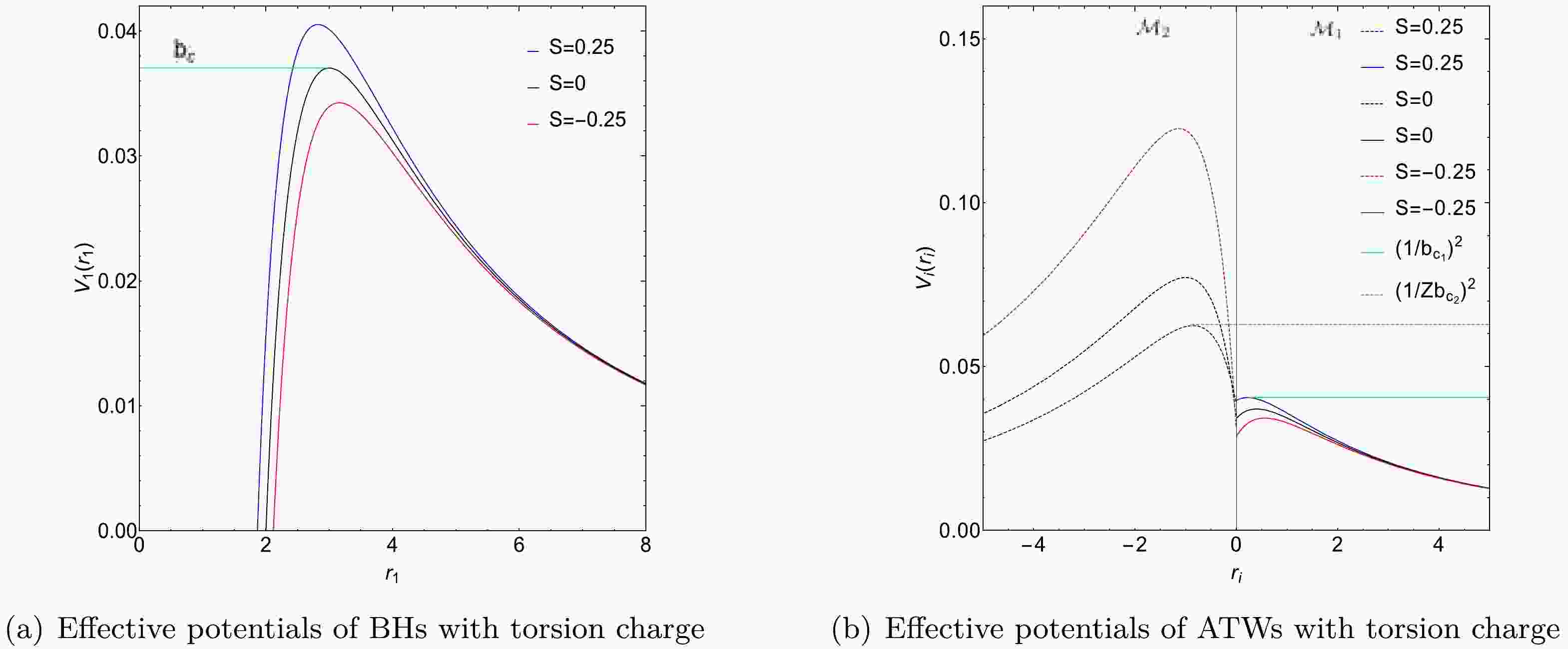
${\cal{S}}$ :$-0.25,~ -0.15,$ 0, 0.15, 0.25. For spacetime${\cal{M}}_1$ , we set$M_1 = 1$ , whereas for spacetime${\cal{M}}_2$ ,$M_2 = 1.2$ .Figure 1 shows the effective potentials for the BH under torsion charge and the corresponding ATW configurations. Fig. 1(a) depicts three distinct photon trajectories: (1) for
$ b < b_{c} $ , photons are absorbed by the BH; (2) for$ b = b_{c} $ , photons follow a stable circular orbit; (3) for$ b > b_{c} $ , photons are deflected owing to gravitational forces. Moreover, Fig. 1(a) also shows that the peak of the effective potential rises as the torsion charge$ {\cal{S}} $ increases, indicating increased gravitational influence at higher torsion charges.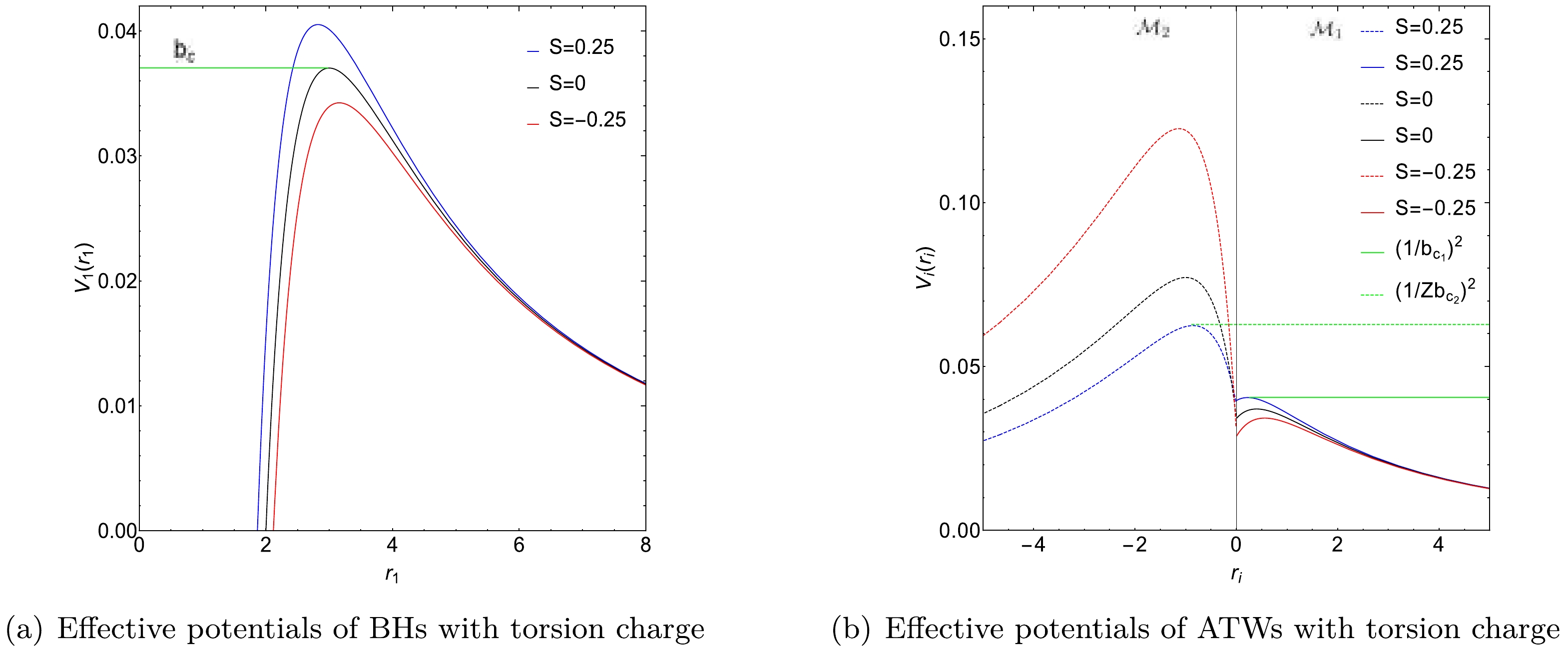
Figure 1. (color online) Effective potentials of BHs and ATWs with torsion charge
${\cal{S}}$ . Three distinct torsion charges are considered:${\cal{S}}=-0.25,\,0,\,0.25$ . The left panel corresponds to the BH scenario while the right panel presents the ATW scenario. For ATWs with torsion charge, the effective potentials within spacetime${\cal{M}}_1$ and spacetime${\cal{M}}_2$ are shown as solid and dashed lines, respectively. Specifically, for a torsion charge${\cal{S}}=0.25$ , the critical impact parameters are$b_{c_1}=4.96791$ (represented by the green line) and$Zb_{c_2}=3.89320$ (represented by the dashed green line). The parameters used in this analysis are$M_1=1,\, M_2=1.2$ , and$R=2.6$ .In Fig. 1(b), for the ATW, the effective potential
$ V_{2}(r_{2}) $ in spacetime$ {\cal{M}}_2 $ is rescaled by a factor of$ Z^2 $ . When analyzing photon trajectories for a given impact parameter$ b_1 $ and fixed torsion charge$ {\cal{S}} = 0.25 $ , three distinct behaviors are observed in spacetime$ {\cal{M}}_1 $ : (1) for$ b_1 < Zb_{c_2} = 3.89320 $ , photons move from$ {\cal{M}}_1 $ to$ {\cal{M}}_2 $ and subsequently escape to infinity within$ {\cal{M}}_2 $ ; (2) for$ Zb_{c_2} < b_1 < b_{c_1} = 4.96791 $ , photons reach a turning point within$ {\cal{M}}_2 $ and then return to$ {\cal{M}}_1 $ ; (3) for$ b_1 > b_{c_1} $ , photons encounter a turning point within$ {\cal{M}}_1 $ and return to infinity in the same spacetime. In this plot, the critical impact parameters are represented by green and dashed green lines, representing$ 1/b_{c_1}^2 $ and$ 1/Zb_{c_2}^2 $ , respectively.To study the optical characteristics of the ATW under torsion charge, it is important to calculate the trajectory and deflection angle of photons traversing the ATW spacetime. According to Eq. (4), the trajectory of a photon is given by
$ \frac{1}{b_{i}^2}-\frac{N_{i}\left(r_{i}\right)}{r_{i}^2} = \frac{1}{r_{i}^4}\left(\frac{\mathrm{d} r_{i}}{\mathrm{d} \phi_{i}}\right)^2. $

(10) To simplify the calculations, we introduce
$ x \equiv 1/r $ , and the equation of motion of the photon is transformed into$ G_i\left(x_i\right) = \left(\frac{{\rm d} x_i}{{\rm d} \phi}\right)^2 = \frac{1}{b_i^2}-x_i^2\left(1-2 M_i x_i+x_i^2 {\cal{S}}\right). $

(11) For
$ b_1 < Zb_{c_2} $ , the photon drops into spacetime$ {\cal{M}}_2 $ and finally escapes to infinity in$ {\cal{M}}_2 $ , thus precluding the need to consider the deflection angle. For$ b_1 > b_{c_1} $ , the photon remains within spacetime$ {\cal{M}}_1 $ , and its turning point is the minimum positive root of$ G_1(x_1) = 0 $ , denoted by$x_1^{\min}$ . Using Eq. (11), the total azimuthal change, or deflection angle, for the photon in spacetime$ {\cal{M}}_1 $ is given by$ \phi_1\left(b_1\right) = 2 \int_0^{x_1^{\min}} \frac{{\rm d} x_1}{\sqrt{G_1\left(x_1\right)}}, \quad b_1>b_{c_1} . $

(12) For
$ Zb_{c_2} < b_1 < b_{c_1} $ , the photon reaches a turning point in spacetime$ {\cal{M}}_2 $ and then returns to$ {\cal{M}}_1 $ . In spacetime$ {\cal{M}}_1 $ , the deflection angle is$ \phi_1^*\left(b_1\right) = \int_0^{1/R} \frac{{\rm d} x_1}{\sqrt{G_1\left(x_1\right)}}, \quad b_1<b_{c_1}. $

(13) For the photon in spacetime
$ {\cal{M}}_2 $ , the turning point$x_2^{\max}$ is found by solving$ G_2(x_2) = 0 $ for its maximum positive root. The corresponding impact parameter$ b_2 $ is determined using Eq. (9). Consequently, the deflection angle of the photon in spacetime$ {\cal{M}}_2 $ is calculated as$ \phi_2\left(b_2\right) = 2 \int_{x_2^{\max}}^{1/R} \frac{{\rm d} x_2}{\sqrt{G_2\left(x_2\right)}}, \quad b_2>b_{c_2} . $

(14) Using Eqs. (12)−(14), we can depict the trajectories of photons within the ATW spacetime, as presented in Fig. 2. Taking the torsion charge
$ {\cal{S}} = 0.25 $ as a representative case, the impact parameter satisfies the condition$ Zb_{c_2}<b_1<b_{c_1} $ , as illustrated in Figs. 2(a), 2(b), and 2(c). For photons originating from infinity in spacetime$ {\cal{M}}_1 $ , it is observed that as the impact parameter$ b_1 $ becomes smaller, the trajectory length within spacetime$ {\cal{M}}_2 $ increases. Fig. 2 shows in the left (Figs. 2(a), 2(d), and 2(g)) and right (Figs. 2(b), 2(e), and 2(h)) columns that a decrease in the torsion charge results in an increase in$ b_{c_1} $ , while$ Zb_{c_2} $ decreases.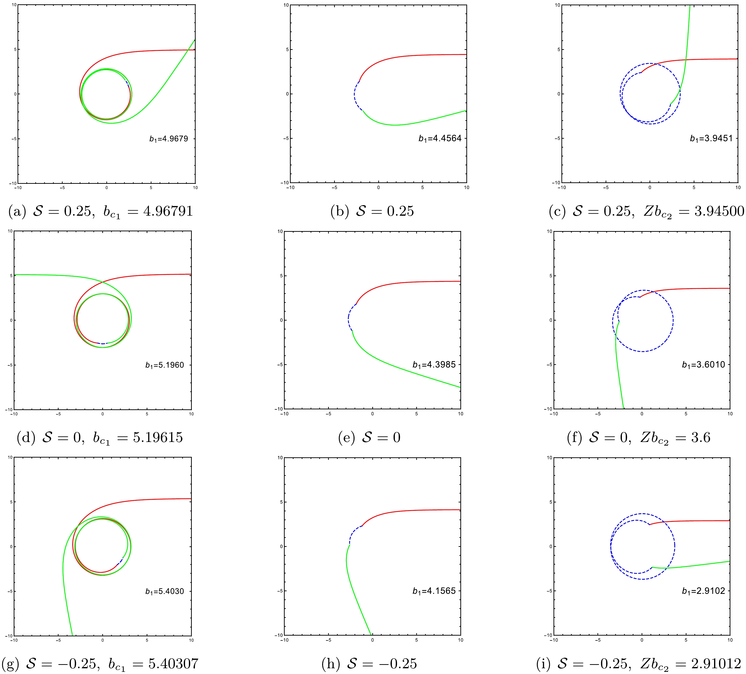
Figure 2. (color online) Trajectories of photons for an impact parameter satisfying
$Zb_{c_2} < b_1 < b_{c_1}$ and an ATW under varying torsion charge${\cal{S}}$ :$0.25,\,0,\,-0.25$ . The red solid lines represent incoming photons in spacetime${\cal{M}}_1$ , the blue dashed lines indicate photons moving through spacetime${\cal{M}}_2$ , and the green solid lines represent outgoing photons in spacetime${\cal{M}}_1$ . For this analysis, we set$M_1=1, M_2=1.2$ , and$R=2.6$ . -
An incoming photon with a specific impact parameter undergoes a reflection process in the ATW, leading to a different observable appearance compared to a BH. In this context, we next analyze the optical appearance of an ATW under torsion charge encircled by an optically and geometrically thin accretion disk. We use two emission models to compare the optical appearances of ATWs and BHs. Given the distinct reflection mechanism of ATWs, its observable features deviate significantly from those of a BH. We consider an observer positioned at the North Pole in spacetime
$ {\cal{M}}_1 $ for both the ATW and BH scenarios to illustrate these differences. -
We define the total orbital number of a photon, which quantifies the complete cycles the photon makes around a BH, as
$ n = \phi / 2 \pi. $

(15) Given that the deflection angle is influenced by the impact parameter, it follows that the total number of orbits is also a function of this parameter. For a BH with an equatorial plane, an observer is positioned at infinity on the North Pole, while the light source is placed at infinity on the South Pole. Depending on the total orbital number n, light near the BH can be categorized into three types: (1) when
$ n < 3/4 $ , the photon intersects the equatorial plane only once, which is classified as direct emission; (2) when$ 3/4 < n < 5/4 $ , the photon crosses the equatorial plane twice, forming a lensing ring; (3) for$ n > 5/4 $ , the photon crosses the equatorial plane at least three times, forming a photon ring [16].In the context of the ATW, for photons with an impact parameter satisfying
$ Zb_{c_2} < b_1 < b_{c_1} $ that originate in spacetime$ {\cal{M}}_1 $ , they will move into spacetime$ {\cal{M}}_2 $ . The definition of the orbital number is modified as follows [73]:$ n_{1}(b_{1}) = \frac{\phi_{1}(b_{1})}{2\pi}, $

(16) $ n_{2}(b_{2}) = \frac{\phi^*_{1}(b_{1}) + \phi_{2}(b_{1}/Z)}{2\pi}, $

(17) $ n_{3}(b_{1}) = \frac{2 \phi^*_{1}(b_{1}) + \phi_{2}(b_{1}/Z)}{2\pi}, $

(18) where
$ n_{2} $ and$ n_{3} $ are additional orbit functions specific to the ATW, representing the extra photon rings resulting from the trajectory of the photon through both spacetimes,$ {\cal{M}}_1 $ and$ {\cal{M}}_2 $ . This redefinition of the orbital number reflects the dynamics of photon orbits in the ATW, distinguishing it from the simpler BH scenario. In the ATW framework, the trajectory of a photon is influenced by its movement between different spacetimes, leading to the formation of extra photon rings that are not present in the BH case. These additional rings provide unique observational signatures that can be used to differentiate an ATW from a traditional BH when observed from the North Pole in spacetime$ {\cal{M}}_1 $ .Figure 3 shows the relationship between orbital numbers
$ n_{1,2,3} $ and impact parameter$ b_1 $ for photons. The orbit number$ n_1 $ is shown in Fig. 3(a). Note that the orbital behavior of an ATW is similar to that of a BH, with the photon remaining within spacetime$ {\cal{M}}_1 $ . When a photon moves into spacetime$ {\cal{M}}_2 $ and subsequently returns to$ {\cal{M}}_1 $ , there are two scenarios: (1) if$ n_2 < 3/4 $ (represented by solid lines in Fig. 3(b)) and$ n_3 > 3/4 $ (represented by dashed lines in Fig. 3(b)), the photon will intersect with the thin accretion disk on the back side; (2) if$ n_2 < 5/4 $ and$ n_3 > 5/4 $ , the intersection will occur on the front side of thin accretion disk. Additionally, Fig. 3(b) shows that an increase in the torsion charge$ {\cal{S}} $ results in a decreased range for the impact parameter$ b_1 $ . This suggests that higher values of$ {\cal{S}} $ cause the additional photon rings to contract towards the inner regions of the ATW shadow. These observations align with the results in Table 1.
Figure 3. (color online) Orbital numbers of the photon around an ATW under different torsion charges:
${\cal{S}} = -0.25$ (red lines),${\cal{S}} = 0$ (black lines), and${\cal{S}} = 0.25$ (blue lines). The left panel shows the orbital number$n_1$ , while the right panel shows the orbital numbers$n_2$ (solid lines) and$n_3$ (dashed lines). For this analysis, we set$M_1=1, M_2=1.2$ , and$R=2.6$ . -
We next analyze the emission from a thin accretion disk surrounding the ATW positioned in spacetime
$ {\cal{M}}_1 $ . For simplicity, we assume a static observer located at the North Pole, with the thin accretion disk lying in the equatorial plane. In the rest frame of this observer, the emission of the disk appears isotropic. Owing to the spherical symmetry of spacetime$ {\cal{M}}_1 $ , the specific intensity of the emitted radiation is a function of the radial coordinate r, represented as$ I^{\rm{em}}_\nu(r) $ , where ν denotes the emission frequency in the static frame. Consequently, we obtain$ \frac{I_{\nu^{\prime}}^{\mathrm{obs}}}{\nu^{\prime 3}} = \frac{I_\nu^{\mathrm{em}}}{\nu^3}. $

(19) The observed specific intensity can be expressed as
$ I_{\nu^{\prime}}^{\mathrm{obs}} = f^{3 / 2}(r) I_\nu^{\mathrm{em}}(r). $

(20) Integrating Eq. (20) yields the total observed intensity at each intersection:
$ I^{\mathrm{obs}} = \int I_{\nu^{\prime}}^{\mathrm{obs}} {\rm d} \nu^{\prime} = \int f^2 I_\nu^{\mathrm{em}} {\rm d} \nu = f^2(r) I^{\mathrm{em}}(r), $

(21) where
$I^{\mathrm{em}}(r) = \int I_\nu^{\mathrm{em}}{\rm d}\nu$ represents the total emitted intensity. Therefore, the total observed intensity is given by$ I_{\text {obs }}(b) = \left.\sum\limits_n I^{\mathrm{em}}(r) f^2(r)\right|_{r = r_n(b_1)}. $

(22) The transfer function
$ r_n(b_1) $ represents the radial coordinate at the n-th intersection of a photon with impact parameter$ b_1 $ and thin accretion disk. This function characterizes the precise location where the trajectory of the photon intersects the disk. Additionally, the rate of change of the transfer function with respect to the impact parameter, denoted as$ {\rm{d}}r/{\rm{d}}b_1 $ , is known as the demagnification factor. The first transfer function ($ n = 1 $ ) is associated with the "direct emission". The second transfer function ($ n = 2 $ ) corresponds to the "lensing ring". The third transfer function ($ n = 3 $ ) describes the "photon ring". These transfer functions are important for interpreting how photons traverse the curved spacetime and how the resultant observational signatures emerge. Figure 4 shows the transfer functions as functions of the impact parameter considering different torsion charges:${\cal{S}} = 0.25, \, 0, -0.25$ . Figure 4(a) shows the transfer functions for a torsion charge$ {\cal{S}} = 0.25 $ . It can be seen that the first transfer function generates a "direct image" with a minimal demagnification factor, indicating the redshift of the source profile. The second transfer function creates the "lensing ring," characterized by a substantial demagnification factor and representing a diminished image of the back side of the disk. The third transfer function produces the "photon ring," which has an even greater demagnification factor, resulting in a significantly reduced image of the front side of the disk.
Figure 4. (color online) Transfer functions of an ATW under different torsion charges
${\cal{S}}$ :$0.25,\,0,\,-0.25$ . The first transfer function is represented by black lines, the second is represented by blue lines, and the third is represented by red lines. For this analysis, we set$M_1=1, M_2=1.2$ , and$R=2.6$ .When comparing the ATW scenario with the BH case, we find a new second transfer function (
$ n = 2 $ ) for the ATW, represented by the blue dashed line, corresponding to the "lensing band". Additionally, near the critical curves$ Zb_{c_2} $ and$ b_{c_1} $ , we observe new third transfer functions ($ n = 3 $ ), represented by red dashed lines, which relate to the "photon ring group" [73, 74]. Furthermore, by calculating the demagnification factors of these second transfer functions for different torsion charges$ {\cal{S}} $ [see the dashed blue lines in Fig. 4], it becomes clear that a decrease in the torsion charge$ {\cal{S}} $ results in a higher demagnification factor for the new second transfer function. -
To study the optical appearance of ATWs, two different emission models of the thin accretion disk are considered. The observed image of an ATW strongly depends on these models. The emission from a thin accretion disk can be approximated using a Gaussian function. For the spacetime manifold
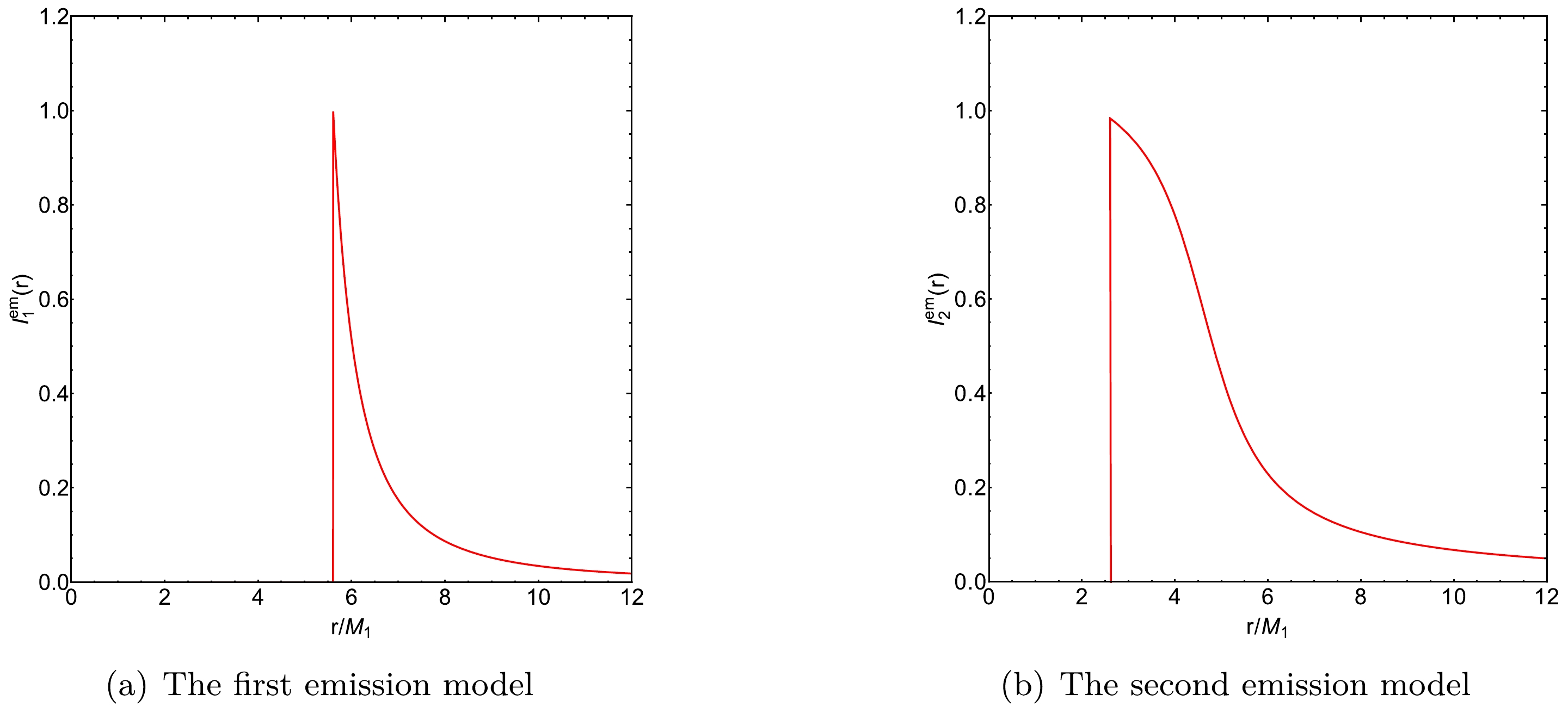
$ {\cal{M}} $ with$ M_{1} = 1 $ , the innermost stable circular orbit, denoted as$r_{\rm isco}$ , can be calculated. For the first emission model, the radiation function is given by$ I_1^{\mathrm{em}}(r) = \begin{cases}0, & r<r_{\rm i s c o}, \\ \left(\dfrac{1}{r-\left(r_{\rm isco}-1\right)}\right)^2, & r \geq r_{\rm isco}.\end{cases} $

(23) Here,
$ r_{\rm isco} $ signifies the inner boundary of the thin accretion disk, indicating that no radiation is emitted from regions within this boundary. The radiation function described by Eq. (23) is shown in Fig. 5(a).The first emission model was used to generate the observed intensity and density plots of an ATW under torsion charge
$ {\cal{S}} = 0.25 $ , as depicted in the top panels of Fig. 6. The Schwarzschild ATW case is also represented in the middle panels of Fig. 6. For comparison, the optical appearance of a BH with the same parameters under the first emission model is represented in the bottom panels of Fig. 6. Figs. 6(a), 6(d), and 6(g) exhibit a distinct spatial separation between the photon ring, lensing band, and direct emission. For an ATW under torsion charge$ {\cal{S}} = 0.25 $ , direct emission with an initial intensity of$ 0.429 $ is observed near the critical curve$ b_1 \simeq 6.605M_{1} $ , and then diminishes, as shown in Fig. 6(a). Moreover, the lensing band is confined between the critical curves$ b_1 \simeq 5.316M_{1} $ and$ b_1 \simeq 6.006M_{1} $ . Photon rings are observed near the critical curves$ b_1 \simeq 3.913 M_{1} $ ,$ b_1 \simeq 4.921 M_{1} $ , and$b_1 \simeq 5.049M_{1}$ . Concerning the optical appearance of the Schwarzschild ATW case, Fig. 6(d) shows that direct emission occurs near the critical curve$ b_1 \simeq 6.928M_{1} $ with an initial intensity of$ 0.442 $ . Furthermore, the lensing band is found near the critical curve$ b_1 \simeq 5.477M_{1} $ . It is also shown that under the first emission model, the higher value of the torsion charge$ {\cal{S}} $ shifts the starting positions of both direct emissions and lensing bands inward. When comparing the ATW case with the BH case in Figs. 6(a) and 6(g), two additional photon rings are observed near the critical curves$ b_1 \simeq 3.913 M_{1} $ and$ b_1 \simeq 4.921 M_{1} $ in the ATW scenario. The corresponding density and local density plots, shown in Figs. 6(b) and 6(c), respectively, reveal that direct emission occurs at the edge of the black disk, while the lensing band is confined within this black disk. Compared with the BH case shown in Figs. 6(h) and 6(i), the ATW scenario features two additional photon rings near the center of the black disk.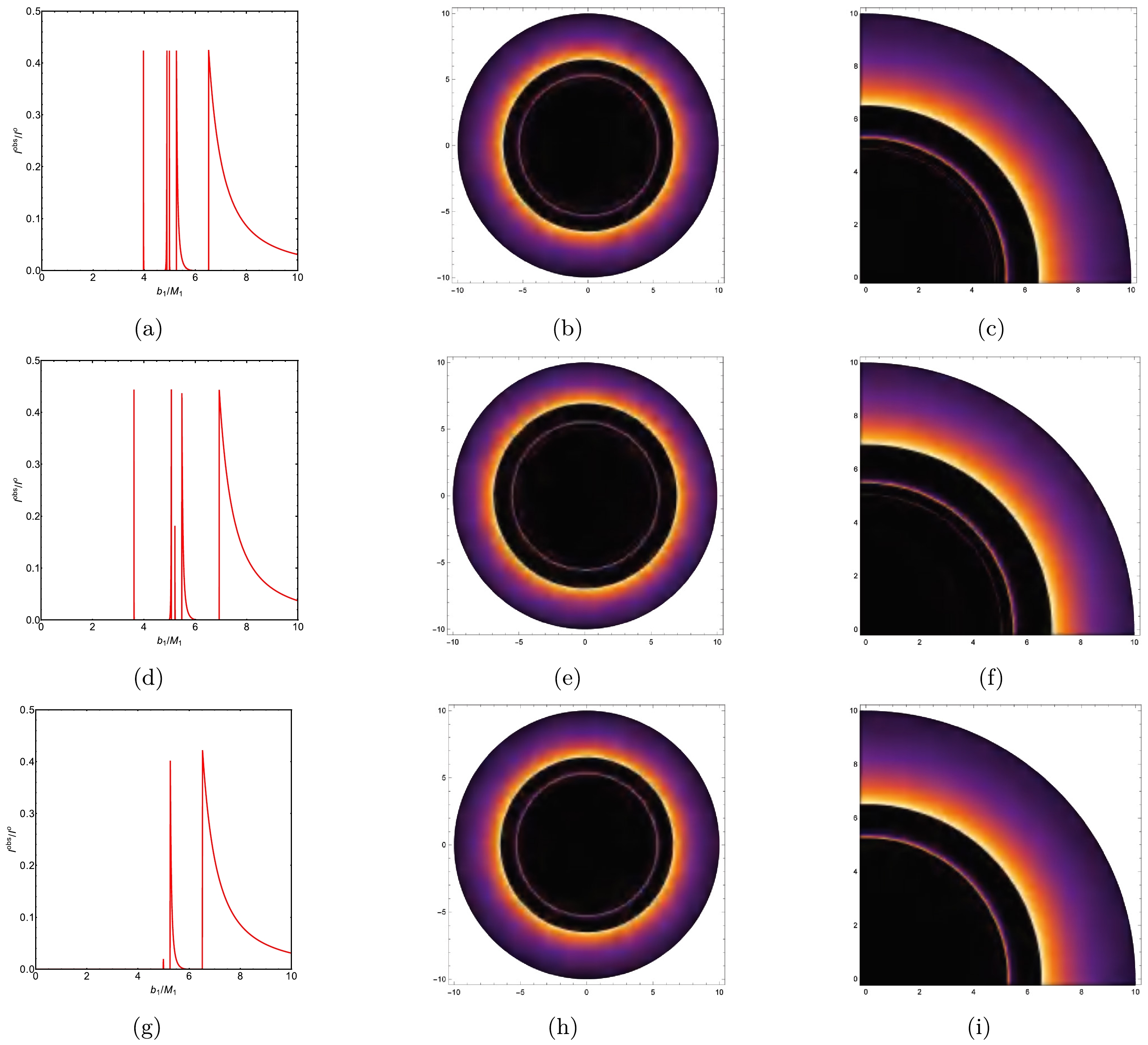
Figure 6. (color online) The observed intensity, density plot, and local density plot of an ATW under a torsion charge
${\cal{S}}=0.25$ resulting from the first emission model are shown in the top panels; the plots of the Schwarzschild ATW are shown in the middle panels; and the plots of the BH under torsion charge${\cal{S}}=0.25$ are displayed in the bottom panels. For this analysis, we set$M_1=1, M_2=1.2$ , and$R=2.6$ .For the second emission model, the radiation function is defined as
$ I_2^{\mathrm{em}}(r) = \begin{cases} 0, & r < r_{h}, \\ \dfrac{\dfrac{\pi}{2} - \tan^{-1}\left(r - \left(r_{\rm isco} - 1\right)\right)}{\dfrac{\pi}{2} - \tan^{-1}\left(r_{ph}\right)}, & r \geq r_{h}, \end{cases} $

(24) where
$ r_{h} $ represents the radius of the event horizon. Thus, there is no radiation emitted from regions smaller than the event horizon. The radiation function described by Eq. (24) is plotted in Fig. 5(b). Compared with the first emission model, the radiation function in the second model decreases more gradually. The observed intensity and density plots of an ATW under a torsion charge$ {\cal{S}} = 0.25 $ obtained from the second emission model are shown in the top panels of Fig. 7. The optical appearances of the Schwarzschild ATW and BH under a torsion charge$ {\cal{S}} = 0.25 $ are also shown in the middle and bottom panels of Fig. 7, respectively. According to Figs. 7(a), 7(d), and 7(g), we observe an overlap between direct emission, lensing band, and photon rings for both the ATW and BH scenarios. For the ATW case under torsion charge$ {\cal{S}} = 0.25 $ , direct emission appears near the critical curve$ b_1 \simeq 2.751M_{1} $ , as shown in Fig. 7(a). Figs. 7(b) and 7(c) show a multi-layered luminous ring structure, with photon rings enclosed within the lensing band. By comparing Figs. 7(a) and 7(g), one can find that the presence of an additional lensing band appears between the critical curves$ b_1 \simeq 4.134 $ and$ b_1 \simeq 5.013 $ . For the Schwarzschild ATW case, Fig. 7(d) indicates that the direct emission occurs near the critical curve$ b_1 \simeq 2.912M_{1} $ . Moreover, an additional lensing band is found between the critical curves$ b_1 \simeq 3.752 $ and$ b_1 \simeq 5.223 $ . Note that under the second emission model, a higher value of the torsion charge$ {\cal{S}} $ shifts the starting position of the direct emission inward, which is consistent with the results observed under the first emission model.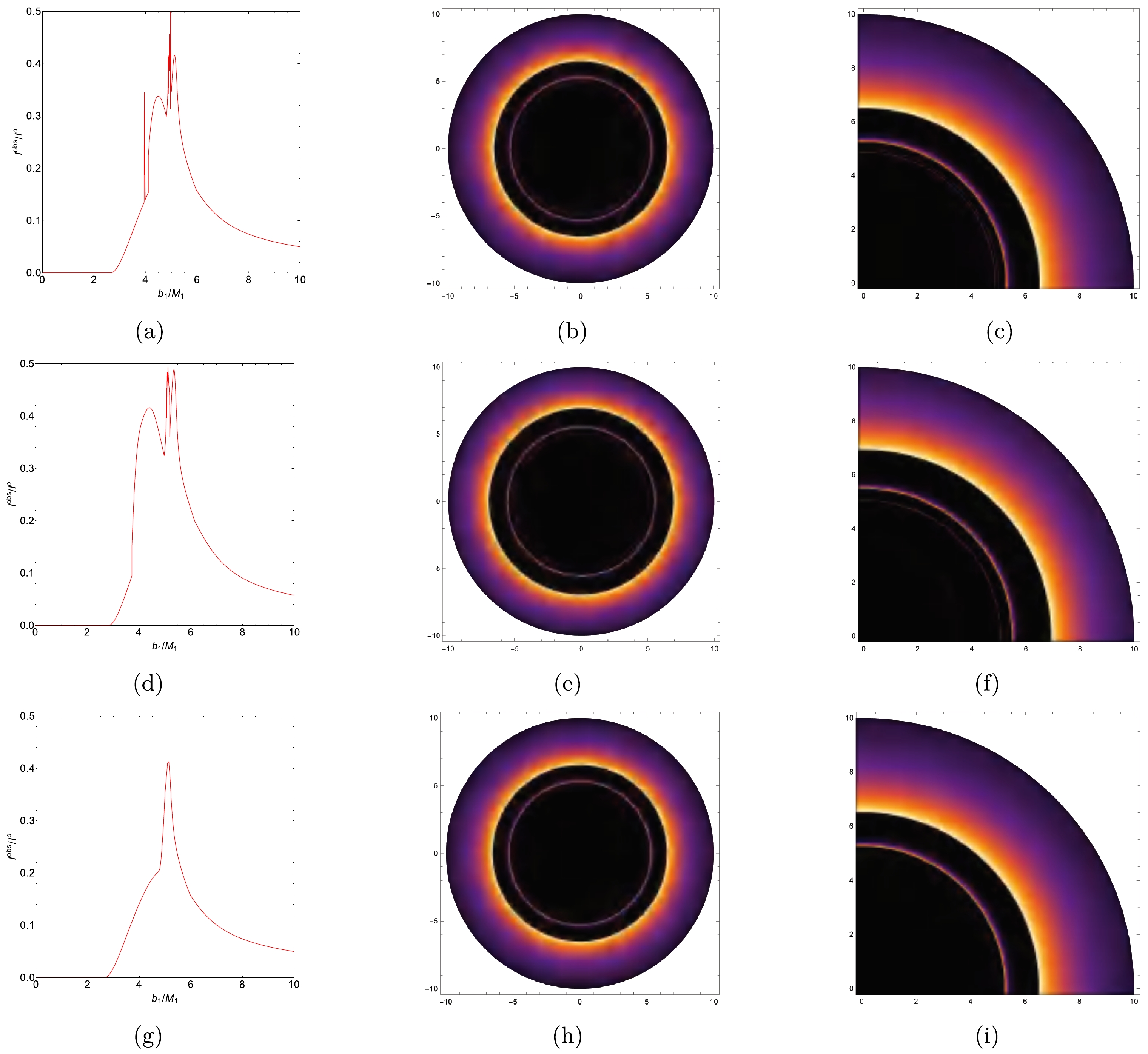
Figure 7. (color online) The observed intensity, density plot, and local density plot of an ATW under a torsion charge
${\cal{S}}=0.25$ resulting from the second emission model are shown in the top panels; the plots of the Schwarzschild ATW are shown in the middle panels; and the plots of the BH under torsion charge${\cal{S}}=0.25$ are displayed in the bottom panels. For this analysis, we set$M_1=1, M_2=1.2$ , and$R=2.6$ . -
In this paper, we study the optical appearance of ATWs under torsion charge. We use the cut-and-paste technique to construct an ATW with two spacetime regions, namely
$ {\cal{M}}_{1} $ and$ {\cal{M}}_{2} $ . In this configuration, a static observer is placed in$ {\cal{M}}_{1} $ , and we calculate key physical properties such as the radius$ r_{ph} $ of the photon sphere and critical impact parameter$ b_{c_{i}} $ . Our findings indicate that increasing the torsion charge$ {\cal{S}} $ results in a reduction in both$ r_{ph} $ and$ b_{c_{i}} $ . This implies that a higher$ {\cal{S}} $ causes the photon sphere to contract towards the shadow center. The effective potentials of ATWs and BHs under torsion charge are depicted in Fig. 1. For the ATW case, depending on the impact parameter of the photon, its trajectory can be categorized into three scenarios: (1) for$ b_1 < Zb_{c_2} $ , the photon moves from$ {\cal{M}}_1 $ to$ {\cal{M}}_2 $ and escape to infinity within$ {\cal{M}}_2 $ ; (2) for$ Zb_{c_2} < b_1 < b_{c_1} $ , the photon reaches a turning point within$ {\cal{M}}_2 $ and then returns to$ {\cal{M}}_1 $ ; (3) for$ b_1 > b_{c_1} $ , the photon reaches a turning point within$ {\cal{M}}_1 $ and returns to infinity in the same spacetime.The light trajectories and deflection angles of photons are studied and plotted in Fig. 2. For photons originating from infinity in spacetime
$ {\cal{M}}_1 $ , we find that that as the impact parameter$ b_1 $ becomes smaller, the trajectory length within spacetime$ {\cal{M}}_2 $ increases. Furthermore, a decrease in the torsion charge results in an increase in$ b_{c_1} $ , while$ Zb_{c_2} $ decreases. The relationship between the orbital numbers$ n_{1,2,3} $ and impact parameter$ b_1 $ for photons within the ATW spacetime is studied. When the photon remains within spacetime$ {\cal{M}}_1 $ , the corresponding orbital behavior for an ATW is similar to that of a BH. When the photon moves into spacetime$ {\cal{M}}_2 $ and returns to$ {\cal{M}}_1 $ , there are two cases for the intersection of the photon and thin accretion disk. As the torsion charge$ {\cal{S}} $ increases, the range of the impact parameter$ b_1 $ decreases. This indicates that higher values of$ {\cal{S}} $ cause the additional photon rings to shrink towards the center of the ATW shadow. These findings are consistent with the results shown in Table 1. Compared with BHs, ATWs exhibit additional transfer functions. The second transfer function is associated with the lensing band, while the third one is associated with the photon ring group.Two different emission models of thin accretion disk are used to study the optical appearances of both ATWs and BHs. For the first emission model, our results show that two additional photon rings appear near critical curves
$ b_1 \simeq 3.913 M_{1} $ and$ b_1 \simeq 5.049 M_{1} $ . Under the second emission model, we observe an extra lensing band located between critical curves$ b_1 \simeq 3.752 $ and$ b_1 \simeq 5.223 $ . When comparing the optical appearance of an ATW under torsion charge and that of the Schwarzschild case, it is observed that increasing the torsion charge$ {\cal{S}} $ shifts the starting position of the direct emission inward. These results suggest that the observational characteristics of ATWs and BHs could serve as a potential method for distinguishing them in future studies.
Effects of torsion charge on optical appearance and additional photon rings of an asymmetric thin-shell wormhole
- Received Date: 2024-07-04
- Available Online: 2024-11-15
Abstract: In this paper, we study the optical properties of asymmetric thin-shell wormholes (ATWs) under torsion charge. Utilizing the cut-and-paste method developed by Visser, we construct these wormholes and determine their key physical properties, such as the radius of the photon sphere and critical impact parameters, under different torsion charges. Furthermore, we investigate the effective potential and behavior of photon motion within the wormhole spacetime, identifying a relationship between photon trajectories and impact parameters. The study focuses on scenarios where thin accretion disks act as the primary light source. It reveals that the optical features of ATWs under torsion charge significantly differ from those of black holes (BHs). Notably, an increase in torsion charge leads to a reduction in the sizes of both extra photon rings and lensing bands, which serve as important markers for distinguishing and characterizing ATW spacetimes from those of BHs.


 Abstract
 HTML
HTML Reference
 Related
 PDF
PDF





 DownLoad: