


 Abstract
 HTML
HTML Reference
 Related
 PDF
PDF


-
Astrophysical observations indicate the existence of cold and collisionless dark matter (DM) that constitutes approximately 85% of the matter in our Universe [1, 2]. While these evidences mostly derive from gravitational effects, a large number of well-motivated particle dark matter candidates have been proposed and extensively searched for; see Ref. [3] for a recent review. A popular scenario assumes dark matter to take the form of a low-mass bosonic field. The extremely small mass of these bosons typically allows for a macroscopic de Broglie wavelength, below which the field behaves coherently. Some well-motivated candidates are the QCD axion [4, 5] and axion-like particles, and the dark photon [6]. Their abundance may originate from the so-called 'misalignment mechanism' [7−10] in the early Universe, and the preferred boson mass and coupling strength to the Standard Model (SM) are predicted by a specific model. Concerning the QCD axion, a natural mass window for it to be the dark matter is
$ {\cal O}(10^{-5}- 10^{-3}) $ eV [11], which corresponds to a converted signal at the microwave energy scale. Regarding axion-like particles and dark photons, wider mass ranges are generally possible.The light bosonic dark matter is often motivated by physics at high energy scale. The couplings to the SM can be highly suppressed, often making the direct-production search at high-energy experiments difficult. Consequently, a class of 'haloscope' experiments have been built based on Sikivie's resonant cavity design [12], in which the cosmic dark matter bosons resonantly convert into an electromagnetic signal in a high Q-factor cavity in case it couples to, or mixes with, the SM photon. In such an experiment, the conversion rate of dark matter is enhanced by the coherence of the light boson field and the cavity resonant mode. Both classical [12] and quantum-level [13] calculations show that a high-Q factor provides a major boost to the signal rate in the frequency range that matches the energy dispersion of the dark matter field, enabling a high sensitivity narrow-band search. Currently, a large number of proposed and ongoing haloscope experiments [14−21] are actively searching for dark matter axions and dark photons; interestingly, this can be potentially applied to high-frequency gravity searches [22, 23].
The extra Lagrangian terms for the dark photon
$ A_d $ dark matter are$ \Delta L \supset -\frac{1}{4}(F_d^{\mu \nu}F_{d\mu \nu} - 2\chi F^{\mu \nu}F_{d\mu \nu} - 2 m_A^{2} A_d^{2}), $

(1) where F and
$ F_d $ respectively denote the field strengths of the Standard Model photon and dark photon,$ m_A $ is a small but nonzero dark photon mass, and χ is the kinetic mixing parameter [24]. The$ \chi\neq 0 $ term mixes the dark photon with the Standard Model photon, enabling the dark matter to incite a photon signal in a haloscope cavity with the signal power [25]$ P_{\rm sig.} = \frac{\beta \eta\chi^2 m_A \rho_{\rm DM} V_{\rm eff}}{\beta+1} L(f, f_0, Q_{l})\,, $

(2) where
$ \beta\sim 0.95 $ is the cavity coupling constant, η is an attenuation factor,$ \rho_{\rm DM} $ is the local dark matter density, the dark photon's mass$ m_A $ is assumed to match the resonant frequency$ f_0 $ of the cavity and receives a resonant enhancement from the cavity's loaded quality factor$ Q_l $ , and$ V_{\rm eff} $ is the cavity's effective volume,$ V_{\rm eff} \equiv \frac{\left| \int {\rm d} V {\boldsymbol E}(\vec{x}) \cdot {\boldsymbol E_d}(\vec{x})\right| ^2}{\int {\rm d} V |{\boldsymbol E}(\vec{x})|^2|{\boldsymbol E_d}(\vec{x})|^2}\,, $

(3) which depends on the overlap between the dark electric field
${\boldsymbol{E}_d}$ and the cavity's resonant mode${\boldsymbol E}$ . L is a Lorentzian detuning factor that describes any off-resonance frequency response in case the measured frequency f differs from$ f_0 $ . Concerning calibration in this study, crucial cavity parameters include the geometric design, resonance frequency$ f_0 $ , and quality factor$ Q_l $ .A cavity haloscope typically searches for narrow-width signals above a thermal noise floor. Relevant sources include the thermal noise of the cavity itself, the added Johnson noise from the amplifier/receiver chain, and quantum fluctuations. For a cavity that operates under the Rayleigh-Jeans limit (
$ k_b T_{\rm sys} \gg hf $ ), its noise power per bandwidth is$ P_n/\Delta f \simeq G k_b T_{\rm cav.} + k_b T_{\rm D}\,, $

(4) where
$ k_b $ and h are respectively the Boltzmann and Planck constants, G is the system gain,$ T_{\rm cav.} $ is the cavity noise temperature, and$ T_{\rm D} $ is the input noise temperature from the amplifier chain. Any signal converted from the dark matter will be captured by the cryogenic amplifiers. To achieve a good signal-to-noise ratio, the measurement must be conducted at a low temperature to reduce the thermal noise from both the cavity and amplifiers.Modern dilution fridges can maintain temperatures below 50 mK, significantly lower than the quantum noise temperature determined by the microwave frequency range. In the haloscope setup, the primary source of noise contamination often arises from the amplifier input noise (dominated by
$ T_D $ ). Commonly used cryogenic amplifiers, such as commercial high electron mobility transistors (HEMTs) [26] can provide good linear amplification at 4 K with added noise around$ {\cal O}(10) $ photons. In principle, Josephson Parametric Amplifiers (JPAs) [27, 28] or Travelling Wave Parametric Amplifiers (TWPAs) [29] can approach the standard quantum limit and offer higher expected sensitivity. Concerning haloscope measurements, critical procedures for estimating the sensitivity also include calibrating the attenuation of input lines, the gain in the amplification channels inside dilution refrigerators, and meticulously measuring the system's noise level.$ T_{\rm cav.} $ is the base temperature of a dilution refrigerator, which is typically below$50\;$ mK.$ T_{\rm D} $ is determined by the noise temperature of preamplifiers used in the experiment and completely dominates the noise temperature in the amplification channels. Conducting weak-signal, high-frequency measurements in an ultra-low-temperature environment presents numerous technical challenges. For example, it is usual to calibrate the attenuation or gain of the measurement system based on a qubit-cavity coupled system via ac Stark shift in superconducting quantum information experiments [30]. However, this method is not suitable for the tunable resonant haloscope cavity experiment because the calibrated parameters are only valid at the fixed cavity frequency. With the development of superconducting quantum technologies, the calibration of a measurement system with broadband frequency range based on a superconducting two-level system or single-photon source has been made possible [31].In this paper, we present the details of essential calibration procedures for the experimental setup of a cryogenic haloscope with a
$ 7.138 $ GHz resonance cavity. We describe the experimental setup and discuss the calibration of the resonance cavity and measurement system in Section II. We performed test measurements with injected signals. Section III presents the calibration procedure and reports on the effective noise temperature of the measurement system. Our results are summarized in Section IV. -
We performed measurements on a cavity device mounted at a
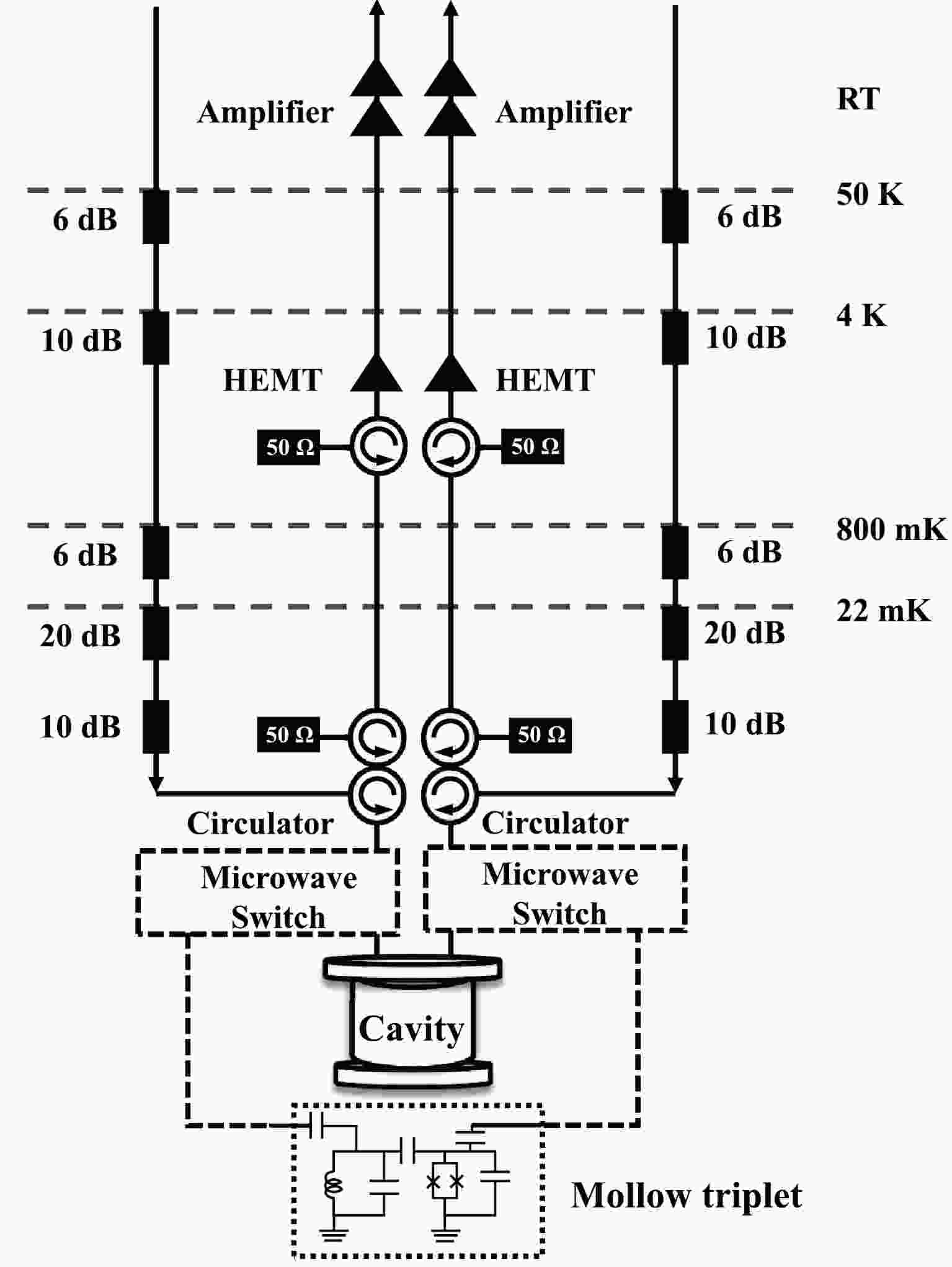
$ 22 $ mK base temperature stage provided by a dilution refrigerator (Model: Bluefors LD 400). The experimental layout is illustrated in Fig. 1. The cavity was located in the$ 22 $ mK stage and contained two identical output ports1 that connected to two detection chains. Each chain included a signal input channel and a signal amplification channel. Given that the target signals are very weak, typically ranging from$ -100\, $ dBm to$ -140\, $ dBm, the most effective approach to suppress the thermal noise is to attenuate the signal together with the noise in input channels. To reduce the leaked thermal noise from room temperature ($ \sim300\, $ K) to the$ 4\, $ K stage, we mounted an attenuator with$ 6\, $ dB attenuation at the$ 50\, $ K stage and another attenuator with$ 10\, $ dB attenuation at the$ 4\, $ K stage. Furthermore, to suppress the thermal noise arising from temperatures higher than the base temperature, we mounted an attenuator with a$ 6\, $ dB attenuation at the Still stage ($ \sim800\, $ mK) and two attenuators with a total of$ 30\, $ dB attenuation at base temperature.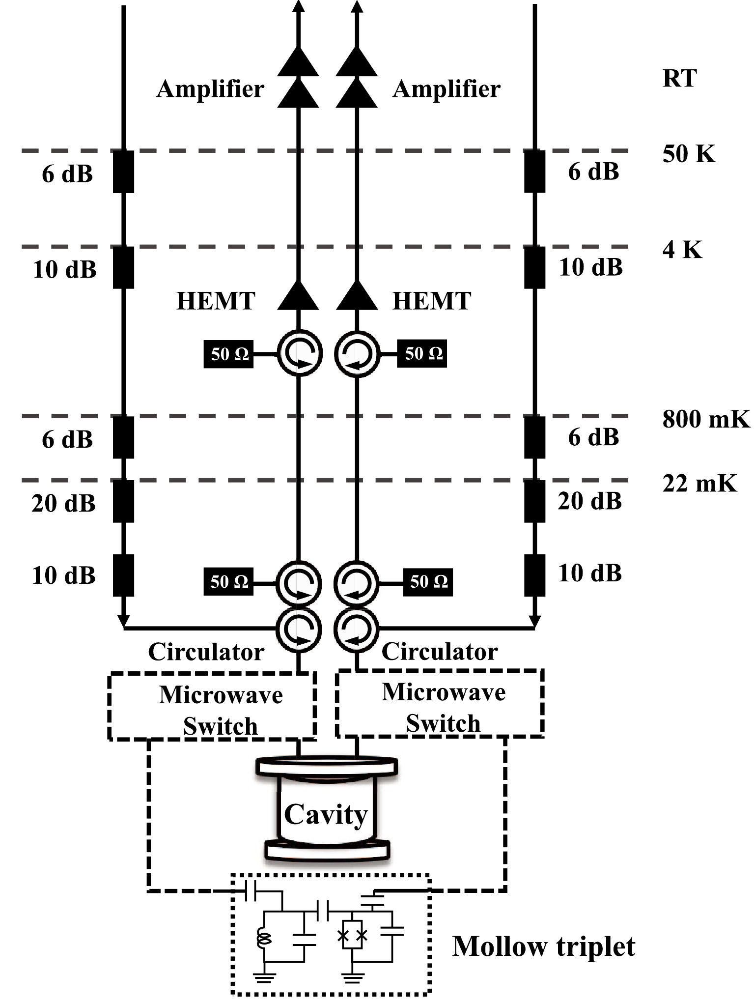
Figure 1. Diagram of the measurement setup for the resonant haloscope cavity. We propose an in situ measuring setup calibration method based on the Mollow triplet of a superconducting two-level system. Both two-position microwave switches regulate either the dark matter search or the system calibration.
In the amplification channel, the weak output signal from the cavity is first amplified by a cryogenic HEMT amplifier (Model:
$ \rm{LNF{—}LNC03\_14A} $ ) at$ 4 $ K with a typical noise temperature$ T_n=4.2 $ K and a gain ($G_{\rm 4K})$ of 36 dB, followed by two amplifiers at room temperature with a total gain$G_{\rm RT}=60\,$ dB at room temperature. Note that the effective noise temperature of the haloscope measurement system is determined by the noise temperature of the first amplifier and the loss between the cavity output port and the amplifier. Therefore, it is helpful to mount a JPA or TWPA, when available, at base temperature as the first amplifier to enhance the sensitivity. To protect the cavity from noise and reflections from the output side, e.g., noise from the cryogenic amplifier, we mounted an isolator (circulator Model$ \rm{LNF{—}CIC4\_12A} $ with one of the three ports terminated with a$ 50\,\Omega $ cryogenic terminator) featuring$ 20\, $ dB isolation at the$ 4\, $ K stage and an isolator featuring$ 20\, $ dB isolation at base temperature. A three-port circulator was mounted at base temperature to connect the input channel, the cavity port, and the output channel to conduct the reflection measurement of the cavity.There was additional attenuation at the coaxial cables as well as insertion loss from different microwave components, e.g., the circulators and cavity output ports. The gain of cryogenic and room-temperature amplifiers may change at different signal frequencies. Therefore, we could only estimate the total attenuation and gain for the input and output channels, respectively. To solve these difficulties, we adopted a method based on a superconducting two-level system [31] to carefully calibrate our measurement system with a broadband frequency range. This method is further explained in Sect. III.
As illustrated in Fig. 2, the cylindrical cavity was constructed from pure copper, with an inner diameter of 32.4 mm, a height of 90 mm, and a thickness of 3 mm. It contained a cylindrical inner resonance volume of 74166
$ \rm{mm^{3}} $ . The lower plane of the cavity was manufactured together with the cavity wall to reduce gaps and losses. The upper surface was tightly connected to the cavity body with eight screws. The inner surface of the cavity was polished to enhance the quality factor of the cavity. Finally, the cavity surface was coated with gold to prevent oxidization. At both ends of the cavity, the cavity wall was appropriately thickened to improve the mechanical strength of the cavity.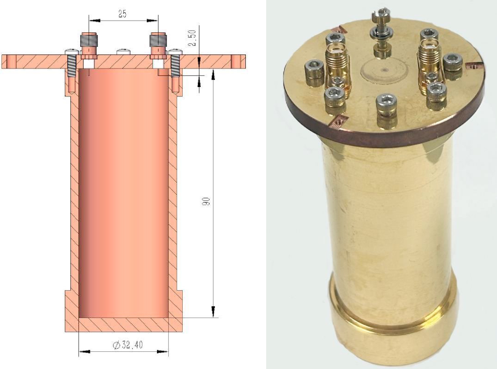
Figure 2. (color online) Cross-section design (left) and exterior (right) of the manufactured resonant cavity.
Two ports (KFD 98 SMA connector) were mounted on the upper surface of the cavity. The connector pins were placed inside the cavity for microwave signal transmission and detection. The width and thickness of the pins are
$ 0.5\, $ mm and$ 0.2\, $ mm, and their length inside the cavity is$ 2.5\, $ mm, which determines the loaded quality factor of the cavity. The four lowest resonance frequencies of the cavity were calculated to be$ 5.6762\, $ GHz ($ \rm{TE_{111}} $ ),$ 7.0853\, $ GHz ($ \rm{TM_{010}} $ ),$ 7.2787\, $ GHz ($ \rm{TM_{011}} $ ), and$ 7.8303\, $ GHz ($ \rm{TM_{012}} $ ). As shown in Fig. 3, we simulated the resonance frequencies around$ \rm{TM_{010}} $ of the cavity with CST software; the copper conductivity was$ 5.96\times10^7\, $ S/m. In the frequency range from$ 6\, $ to$ 7.5\, $ GHz, the simulated frequencies for$ \rm{TM_{010}} $ and$ \rm{TM_{011}} $ were$ 7.0857\, $ and$ 7.2789\, $ GHz, respectively, which agree well with our calculations. We set$ \rm{TM_{010}} $ as the working mode of the cavity because it exhibits a higher form factor in dark matter conversion.
Figure 3. (color online) Simulated cavity transmission spectrum containing the
$ \rm{TM_{010}} $ and$ \rm{TM_{011}} $ modes.We measured the transmission spectrum on the cavity using a vector network analyzer (VNA) by injecting a probe signal through the input channel on one of the cavity's ports and detecting the amplified signal through the output channel on the other port. As shown in the upper and lower panels in Fig. 4, the
$ S_{21} $ spectra of the$ \rm{TM_{010}} $ and$ \rm{TM_{011}} $ modes are presented with an IF frequency of$ 30\, $ Hz. To extract the decay rate of the resonant cavity modes, we injected a signal power$ P = -145\, $ dBm to keep the cavity’s average photon number$ \langle n\rangle=P/2\hbar\omega_c\kappa $ less than 1 for the measurement of the two cavity modes. Then, we fitted the$ S_{21} $ spectra with Lorentzian curves for both modes and extracted resonant frequencies and decay rates. Concerning the$ \rm{TM_{010}} $ mode, the room-temperature resonant frequency was found to be$ \omega_c/2\pi= $ 7.113 GHz, with a decay rate$ \kappa/2\pi= $ 0.72 MHz and a quality factor$ Q_l=9879 $ . Therefore, the experimental measurement results (7.113 GHz) agree well with the corresponding theoretical predictions (7.0853 GHz) and simulation outcomes (7.0857 GHz). The low-temperature (22 mK)$ \rm{TM_{010}} $ frequency was$ \omega_c/2\pi=7.138\, $ GHz, with$ \kappa/2\pi= $ 0.60 MHz and$ Q_l=11897 $ at$ 22\, $ mK. We also measured the$ \rm{TM_{011}} $ mode. The measured resonant frequency was$ \omega_c/2\pi= $ 7.305 GHz; the decay rate was$ \kappa/2\pi= $ 0.99 MHz; and the quality factor was$ Q_l=7379 $ at room temperature; at 22 mK, we measured$ \omega_c/2\pi= $ 7.331 GHz,$ \kappa/2\pi= $ 0.99 MHz, and$ Q_l=7405 $ $ $ .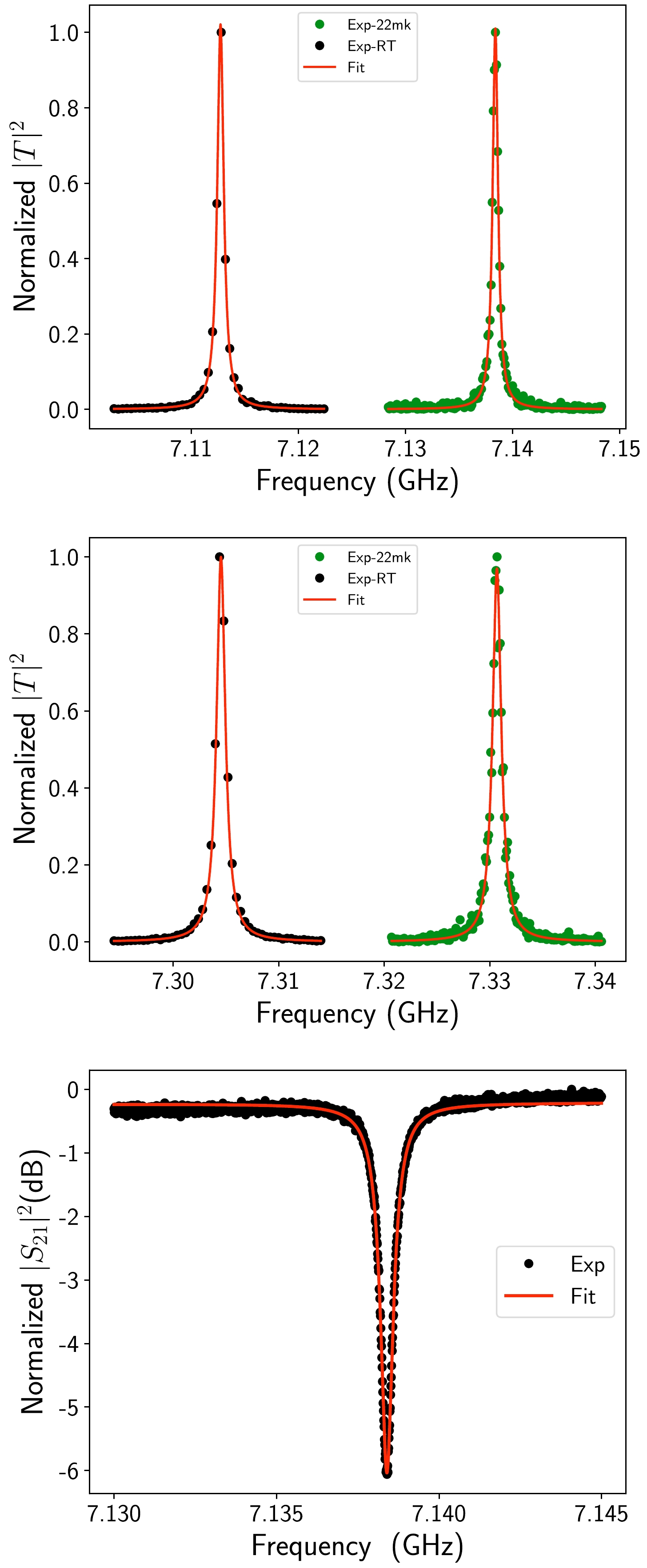
Figure 4. (color online) Test results for the
$ \rm{TM_{010}} $ (upper) and$ \rm{TM_{011}} $ (mid) modes. The lower panel is the reflection measurement of$ \rm{TM_{010}} $ and the fitting results from Eq. (5).To extract the extrinsic quality factor, we also measured the reflection (
$ S_{21} $ ) of the cavity via the three-port circulator at base temperature and fitted it by [32]$\begin{aligned}[b] S_{21} = A \left(1+\alpha \frac{\omega-\omega_c}{\omega_c} \right) \left(1- \dfrac{\dfrac{Q_l}{|Q_e|}{\rm e}^{{\rm i}\theta} }{1+2 {\rm i} Q_l \dfrac{\omega-\omega_c}{\omega_c}} \right) {\rm e}^{{\rm i} (\phi_v \omega + \phi_0)}, \end{aligned} $

(5) where A is the background amplitude,
$ \omega-\omega_c $ corresponds to the detuning of the detected signal and the cavity frequency,$ Q_{l} $ denotes the loaded quality factor,$ Q_{e} $ represents the magnitude of the extrinsic quality factor, θ denotes the phase of the extrinsic quality factor,$ \phi_v $ indicates the phase to accommodate the propagation delay to the sample,$ \phi_0 $ describes the phase to accommodate the propagation delay from the sample, and α characterizes the slope of the signal around the resonance. The fitting results are depicted in the lower plot of Fig. 4, revealing$ Q_{l}= $ 11006 and$ Q_{e}= $ 22544. Note that this value of$ Q_{l} $ , obtained by reflection spectrum fitting, is slightly different from$ Q_{l}= $ 11897, obtained by transmission spectrum fitting. Both modes experience a$ \Delta \omega_c/2\pi\approx +25\, $ MHz frequency shift after cooling from room to base temperature. Moreover, the quality factors of both cavity modes at$ 22\, $ mK are higher than those at room temperature owing to a lower copper resistivity at$ 22\, $ mK. -
Under strong resonant driving, an incoherent emission spectrum typically exhibits three peaks arising from a two-level system; this is known as resonance fluorescence or Mollow triplet [33]. The Mollow triplet can be explained using the dressed-state picture of the driven two-level system [31, 33−35]. In this picture, the two-level system is dressed by the driving field, leading to the formation of new eigenstates called dressed states. These dressed states exhibit energy level splittings, which result in four distinct transitions: the central peak corresponds to the transition between the undressed ground and excited states, while the two side peaks correspond to transitions involving the dressed states. Therefore, the area of each side peak rigorously corresponds to the power of the single-photon
$ \hbar\omega\Gamma_1 $ for different frequencies.The distance between the two side peaks of the Mollow triplet is related to the energy splitting between the dressed states, which in turn depends on the strength of the driving field and the properties of the two-level system. The distance and two side peaks can be used to calibrate the attenuation and gain of the measurement system with high precision [31]. By accurately determining this distance, one can calibrate the frequency scale of the measurement system, allowing for precise measurements of signal amplitudes and spectral features. Here, we present the calibration of the measurement system's attenuation, gain, and noise level in a broadband frequency range based on the Mollow triplet of a superconducting two-level system with nominal identical measurement system. We used the same superconducting two-level system sample for calibration as in Ref. [34].
The transition frequency of a superconducting two-level system can be designed in a broad frequency range, from
$ 1\, $ GHz to$ 12\, $ GHz, and tuned by the biased flux through the sample loop in situ. Therefore, the transition frequency can be set at any frequency in this range for calibration. For example, we set the two-level system at its maximal transition frequency,$ \omega_a/2\pi= $ 10.299 GHz, with smallest dephasing rate and drove it resonantly through an input channel with a coherent microwave field generated by a signal source at room temperature. We measured the Mollow triplet by monitoring the incoherent emission spectrum around$ 10.299\, $ GHz using a spectrum analyzer. The spectral density of the incoherent emission from the two-level system is given by [35]$ \begin{aligned}[b] S(\omega)=\;&\frac{1}{2\pi}\frac{\hbar\omega\Gamma_1}{8}\left(\frac{\Gamma_s}{(\delta\omega+\Omega)^2+\Gamma_s^2}\right. \\ &+\frac{2\Gamma_2}{\delta\omega^2+\Gamma_2^2}+\left.\frac{\Gamma_s}{(\delta\omega-\Omega)^2+\Gamma_s^2}\right), \end{aligned} $

(6) where
$ \Gamma_1/2\pi=4.3\pm0.7\, $ MHz is the relaxation rate,$ \Gamma_2=\Gamma_1/2 $ is the dephasing rate of the two-level system,$ \Gamma_s=(\Gamma_1+\Gamma_2)/2 $ is the linewidth of the side peaks,$ \delta\omega $ is the detuning from the transition frequency, and Ω is the Rabi frequency of the two-level system under resonant driving.The intensity of the Mollow triplet depends on the driving power on-chip (after calibration); this intensity is shown in the upper representation of Fig. 5. The middle representation of Fig. 5 shows the two side peaks in the emission spectrum when the driving power on-chip was around
$ -107\, $ dBm. The distance between the two side peaks is$ 2\Omega=2\pi\times126 $ MHz according to the fitting of the resonance fluorescence spectrum with Eq. (6). We calculated the power sensed by the two-level system using$ W_0= \hbar\omega\Omega^2/(2\Gamma_1) $ . Then, we plotted$ W_{\rm in} $ versus$ W_0 $ using linear fitting. The attenuation, which is given by the slope, was$ -71.4\pm0.2 $ dB in the input channel. High calibration precision can be achieved because the fitting can give a low uncertainty$ \Delta\Omega/\Omega\leq0.01 $ , where$ \Delta\Omega $ is the uncertainty of Ω. The gain of the output line can also be obtained by the Mollow triplet measured by the spectrum analyzer at room temperature. By fitting the two side peaks with Eq. (6), we obtained that the gain of the output channel of our measurement system was$ 95.6\pm1.0 $ dB. With the attenuation and gain calibrated, we could calibrate the emission spectrum measured by a spectrum analyzer. The measured noise spectral density of the HEMT amplifier placed at the$ 4 $ K stage was approximately$ 1.03\times10^{-22} $ W/Hz. Using the expression$2\pi S(\omega)= k_{\rm B}T_{\rm D}$ [35], we deduced that the effective noise temperature of the measurement was around$ 7.5 $ K with an accuracy of approximately$ \pm1 $ dB and an uncertainty determined by the calibrated gain. We calibrated the attenuation, gain, and effective noise temperature at the maximal transition frequency (10.299 GHz) of the two level system. Owing to the frequency difference, there can be some extra uncertainty in the cable attenuation, connector loss, and gain from HEMTs and room amplifiers at 7.138 GHz. The nominal attenuation from microwave cables at$ 7.138 $ GHz is approximately$ 2\, $ dB smaller than that at$ 10.299 $ GHz. The nominal gain from HEMT at$ 7.138\, $ GHz is$ 2 $ dB smaller. There is no nominal difference in the gain of room temperature amplifiers between$ 7.138 $ GHz and$ 10.299 $ GHz. The frequency dependence of total loss from all connectors is more complicated; nevertheless, the total loss should be smaller than$ 2 $ dB. Therefore, we approximately estimated that the attenuation is$ -71.4\pm3\, $ dB, the gain is$ 95.6\pm3\, $ dB, and the effective noise temperature is$ 7.5 $ K with an approximate accuracy of$ \pm3\, $ dB for the measurement system at$ 7.138 $ GHz. This uncertainty from frequency difference can be further removed by follow-up in situ measurements.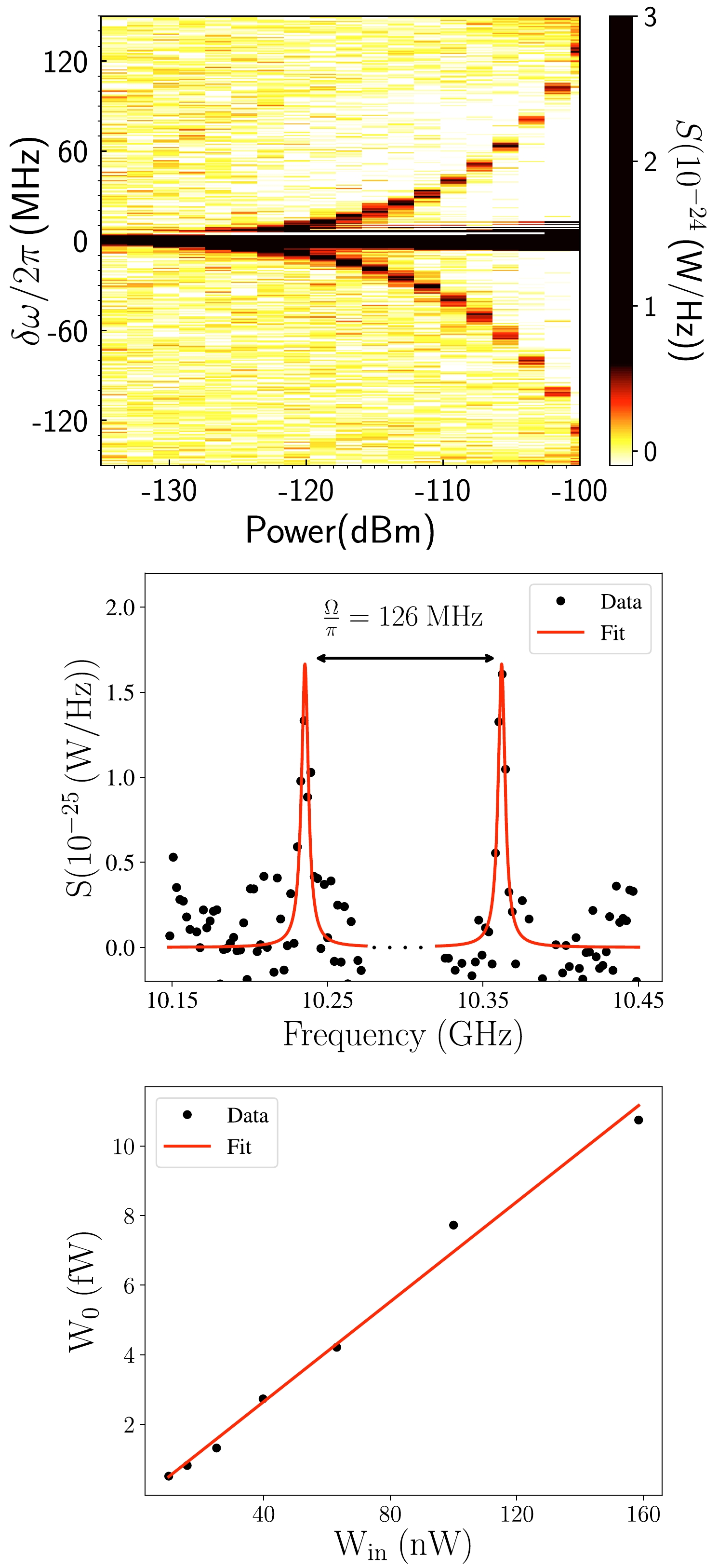
Figure 5. (color online) Attenuation calibration in one cavity input channel. The resonance fluorescence spectrum (upper) is shown for the driving power ranging from
$ -135\, $ dBm to$ -101\, $ dBm with a step of$ 2\, $ dBm. The two side peaks of the Mollow triplet (middle) were measured for a driving power of$ -107\, $ dBm, and the best fitting (red) was derived from Eq. (6). The measured power$ W_0 $ at the two-level system (lower) is shown versus the input power$ W_{in} $ at$ 10.299\, $ GHz and room temperature. The attenuation is given by the slope of the linear fitting. -
We built a resonant haloscope cavity measurement system based on a dilution refrigerator and tested the cavity and measurement system at room temperature and 22 mK. The cylindrical two-port copper cavity features a 74166 mm
$ ^3 $ volume and was designed to operate at 7.138 GHz$ {\rm TM_{010}} $ mode with a low-temperature quality factor$ Q=10^4 $ . We calibrated the attenuation of the input channel, gain in the output channel, and effective noise temperature of the measurement system based on the measurement of the Mollow triplet with a superconducting two-level system. The calibrated attenuation is$ -71.4\pm3\, $ dB, the gain is$ 95.6\pm3\, $ dB, and the effective noise temperature is$ 7.5\, $ K with an accuracy of$ \pm3\, $ dB for our HEMT amplifiers, which contribute the most to the measured noise. In perspective, quantum-limited preamplifiers, such as JPAs and TWPAs, significantly reduce the effective noise temperature in the system. The advantage of the proposed calibration method is its ability for in situ system calibration in a broad frequency range. This method can also be well-suited for frequency-adjustable narrow-band cavity experiments.
Calibration of the cryogenic measurement system of a resonant haloscope cavity
- Received Date: 2024-03-11
- Available Online: 2024-07-15
Abstract: Possible light bosonic dark matter interactions with the Standard Model photon have been searched using microwave resonant cavities. In this paper, we describe the cryogenic readout system calibration of a 7.138 GHz copper cavity with a loaded quality factor


 DownLoad: